Product Description
Please note:
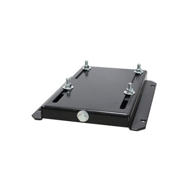
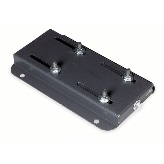
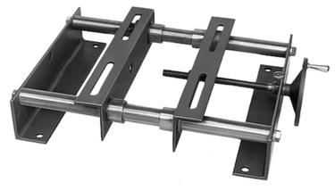
Overall inner packaging: Compact HM30-130 Ball Screw Motor Base 1PCS
You can place your order directly and we will ship it within 24 hours. Please be patient and wait for the goods to arrive
Need to purchase more: Please click on the link to purchase:
featured-list/online-trading-products.html
Welcome to our selection of guide rail accessories, featuring the 1PCS Ball screw motor seat HM10-57. This precision ball screw holder is designed to provide reliable support for your motorized guide rail system. The HM10-57 motor seat is a high-quality linear motion motor bracket that ensures smooth and accurate movement along the guide rail.
Crafted from durable materials, this ball screw assembly bracket is built to last, offering long-term performance and stability. The guide rail mounting bracket is easy to install, making it suitable for a wide range of applications. Whether you are working on a DIY project or a professional industrial application, the HM10-57 motor seat is the perfect choice for your guide rail needs.
Upgrade your equipment with this ball screw motorized support and experience enhanced precision and efficiency in your linear motion systems. Shop now and take your projects to the next level!
Product Description
| Aluminium Linear Ball Bearing Slide Unit | |
| Model number | Supported Liner Rail: SBR16,20,25,30,35,40,50; TBR16,20,25,30 Length:0-6000mm SBR..UU: SBR10UU, SBR12UU, SBR16UU, SBR20UU, SBR25UU, SBR30UU, SBR35UU,SBR40UU, SBR50UU; SBR…LUU:SBR10LUU,SBR12LUU,SBR16LUU,SBR20LUU,SBR25LUU,SBR30LUU,SBR35LUU,SBR40LUU,SBR50LUU TBR..UU: TBR16UU, TBR20UU, TBR25UU, TBR30UU;TBR…LUU:TBR16LUU, TBR20LUU, TBR25LUU, TBR30LUU SCS..UU:SCS6UU,SCS8UU,SCS10UU,SCS12UU,SCS13UU,SCS16UU,SCS20UU,SCS25UU,SCS30UU,SCS35UU,SCS40UU,SCS50UU SCS..LUU:SCS8LUU,SCS10LUU,SCS12LUU,SCS13LUU,SCS16LUU,SCS20LUU,SCS25LUU,SCS30LUU,SCS35LUU,SCS40LUU,SCS50LUU SC..VUU: SC8VUU,SC10VUU,SC12VUU,SC13VUU,SC16VUU,SC20VUU,SC25VUU,SC30VUU,SC35VUU,SC40VUU, SC50VUU SHF..A:SHF8,SHF10,SHF12,SHF13,SHF16,SHF20,SHF25,SHF30,SHF35,SHF40,SHF50 SH..A(SK):SK8,SK10,SK12,SK13,SK16,SK20,SK25,SK30,SK35,SK40,SK50,SK60 |
| Material | Aluminum Alloy |
| Appearance | Anodized surface, high hardness, corrosion resistance, not rust, low noise |
| Application | 3D printer, milling machine, CNC engine lathe, gear shaper, hobbing, precision machine tools, robotics, semiconductor, electric tools, sports equipment, woodworking machinery, food machinery, medical machinery, textile machinery, optical instruments, glass manufacturing, automobile manufacturing equipment, automation equipment, laser engraving, blanket machinery, ceramic tile machinery, printing machinery, electronic industry, man-made board bearing equipment, machinery, paper machinery, plastic machinery, inspection devices, transmission equipment, packaging machinery, textile machinery |
| OEM&Customized | Accepted to drawing |
Material: aluminum alloy
Structure: Rotational motion
characteristic
Lightweight and cost reducing
The system installation and maintenance are simple
High performance dust prevention
High precision, high efficiency, and high reliability
Applicable to
1. Automatic control machine
2. Semiconductor industry
3. General industrial machinery
4. Medical equipment
5. Solar equipment
6. Machine tool
7. Parking system
8. High speed railway and air transportation equipment, etc
/* January 22, 2571 19:08:37 */!function(){function s(e,r){var a,o={};try{e&&e.split(“,”).forEach(function(e,t){e&&(a=e.match(/(.*?):(.*)$/))&&1
| Application: | Warehouse Crane, Shipboard Crane, Goods Yard Crane, Building Crane, Workshop Crane |
|---|---|
| Material: | Steel |
| Structure: | Container Crane |
| Samples: |
US$ 127.71/Set
1 Set(Min.Order) | Order Sample Contact customer service for free samples
|
|---|
| Customization: |
Available
|
|
|---|
.shipping-cost-tm .tm-status-off{background: none;padding:0;color: #1470cc}
|
Shipping Cost:
Estimated freight per unit. |
about shipping cost and estimated delivery time. |
|---|
| Payment Method: |
|
|---|---|
|
Initial Payment Full Payment |
| Currency: | US$ |
|---|
| Return&refunds: | You can apply for a refund up to 30 days after receipt of the products. |
|---|
Are motor bases compatible with different types of motor mounts and couplings?
Motor bases are designed to be compatible with different types of motor mounts and couplings. Here’s a detailed explanation:
1. Motor Mounts: Motor bases typically provide standard mounting options that are compatible with various motor mount configurations. Common motor mount types include:
- Foot Mounts: Motor bases with foot mounts have slots or holes that align with the mounting feet on the motor. These bases allow for secure attachment and proper alignment of the motor.
- Flange Mounts: Some motors have flanges instead of feet for mounting. Motor bases designed for flange-mounted motors have matching flange patterns that ensure proper alignment and secure attachment.
- Face Mounts: In certain applications, motors are mounted directly to a surface using a face mount configuration. Motor bases compatible with face mounts provide the necessary mounting features, such as bolt patterns or mounting brackets, to facilitate this type of installation.
Motor bases are typically available in different configurations to accommodate these various motor mount types. This compatibility ensures that the motor base can securely and correctly mount different motor types, allowing for flexibility and ease of installation.
2. Motor Couplings: Motor bases are not directly involved in the coupling between the motor and driven equipment. The coupling is a separate component that connects the motor shaft to the driven shaft, such as a pump or gearbox. Motor bases do not have specific compatibility requirements with motor couplings.
However, it’s important to consider the space and clearance requirements for the coupling when selecting a motor base. Motor bases should provide adequate space for the coupling and allow for proper alignment between the motor and driven equipment.
Motor bases play a vital role in supporting and aligning the motor, irrespective of the type of motor mount or coupling used. They provide a secure and stable platform for mounting the motor, ensuring proper alignment, minimizing vibrations, and supporting the overall performance of the motor.
When selecting a motor base, it’s essential to consider the motor mount type specified by the motor manufacturer and ensure compatibility with the chosen base. Additionally, considering the space requirements for the motor coupling and its alignment with the driven equipment can help determine the appropriate motor base configuration.
In summary, motor bases are designed to be compatible with different types of motor mounts, including foot mounts, flange mounts, and face mounts. They provide the necessary features and configurations to securely and properly mount the motor. Motor bases are not directly involved in motor coupling, but they should accommodate the space and alignment requirements of the coupling. Considering motor mount compatibility and coupling clearance when selecting a motor base ensures a well-integrated and efficient motor installation.
What are the advancements or innovations in motor base technology?
The field of motor base technology has seen several advancements and innovations in recent years. Here’s a detailed explanation:
1. Smart Motor Bases: One significant advancement is the integration of smart technologies into motor bases. Smart motor bases incorporate sensors, connectivity features, and data analysis capabilities to monitor motor performance, detect anomalies, and provide real-time feedback. These bases can communicate with control systems, enabling predictive maintenance, energy optimization, and remote monitoring.
2. Vibration Control: Motor bases with enhanced vibration control features have emerged to address vibration-related challenges. These bases utilize advanced materials, design techniques, and vibration isolation technologies to minimize the transmission of motor vibrations to the surrounding structure. This helps reduce noise, prevent structural damage, and improve overall system performance.
3. Alignment Assistance: Advancements in alignment assistance have made motor base installation and alignment more efficient. Some motor bases now incorporate built-in alignment guides, laser alignment systems, or augmented reality-based alignment tools. These features assist technicians in achieving precise alignment, reducing installation time and minimizing the risk of misalignment-related issues.
4. Modular Design: Modular motor bases have gained popularity due to their flexibility and ease of installation. These bases consist of standardized modules that can be easily configured and combined to accommodate motors of various sizes and types. The modular design simplifies inventory management, reduces lead times, and allows for quick adaptation to changing motor requirements.
5. Energy Efficiency Enhancements: Motor bases are increasingly designed with energy efficiency in mind. Advancements in materials, construction techniques, and aerodynamics have led to motor bases with reduced energy losses and improved heat dissipation capabilities. Additionally, features like adjustable mounting slots, quick-release mechanisms, and integrated thermal management systems contribute to enhanced energy efficiency.
6. Environmental Considerations: Motor base technology has also evolved to address environmental concerns. Manufacturers are incorporating sustainable materials, optimizing designs for recyclability, and reducing the environmental footprint of motor bases. This includes using eco-friendly coatings, minimizing the use of hazardous substances, and implementing environmentally conscious manufacturing processes.
7. Integration with Condition Monitoring: Motor bases are being integrated with condition monitoring systems to enable proactive maintenance. By integrating sensors for temperature, vibration, and other relevant parameters, motor bases can provide real-time data on motor health. This data can be used to schedule maintenance tasks, detect early signs of failure, and optimize performance.
These advancements in motor base technology have led to improved motor performance, increased energy efficiency, enhanced reliability, and simplified maintenance procedures. As technology continues to advance, motor bases are expected to become even more intelligent, adaptable, and environmentally friendly.
What materials are commonly used in the construction of durable motor bases?
Durable motor bases are constructed using various materials that provide strength, stability, and longevity. Here’s a detailed explanation:
Motor bases are designed to withstand the weight and operational forces of electric motors while maintaining stability and alignment. The choice of materials for motor base construction depends on factors such as the motor size, application requirements, and environmental conditions. Here are some commonly used materials:
1. Steel: Steel is one of the most commonly used materials for motor bases due to its exceptional strength and durability. Motor bases made of steel can withstand heavy loads and resist deformation. Steel motor bases are known for their rigidity, stability, and ability to dampen vibrations. They are suitable for a wide range of motor sizes and industrial applications.
2. Cast Iron: Cast iron is another popular material for motor bases, especially for larger motor sizes. Cast iron offers excellent stability and resistance to deformation under heavy loads. It has high compressive strength and can effectively absorb and dampen vibrations generated during motor operation. Cast iron motor bases are known for their long-lasting performance and suitability for demanding industrial environments.
3. Aluminum: Aluminum motor bases are commonly used for smaller or lighter motor applications. Aluminum is lightweight, corrosion-resistant, and offers good thermal conductivity. Motor bases made of aluminum are easy to handle and install. They are often preferred in applications where weight reduction is desired, such as in portable or mobile equipment.
4. Composite Materials: In some cases, motor bases may be constructed using composite materials such as fiberglass-reinforced plastic (FRP). Composite motor bases offer a combination of strength, lightweight construction, and corrosion resistance. They are particularly suitable for applications where weight reduction, electrical insulation, or resistance to chemicals and corrosive environments are important considerations.
5. Other Materials: Depending on specific requirements, motor bases can also be constructed using other materials such as stainless steel, galvanized steel, or specialized alloys. These materials may be chosen for their specific properties, such as resistance to corrosion, high-temperature applications, or compatibility with certain environmental conditions.
When selecting a motor base material, it’s essential to consider factors such as load capacity, environmental conditions (such as exposure to moisture, chemicals, or extreme temperatures), and the specific needs of the application.
In summary, durable motor bases are commonly constructed using materials such as steel, cast iron, aluminum, composite materials, and other specialized alloys. Each material offers specific advantages in terms of strength, stability, weight, corrosion resistance, and other properties, allowing motor bases to withstand the demands of industrial applications.


editor by CX 2024-04-19
China aslong motor hall sensor Threaded shaft JGY370 M650 DC6V12V24V Screw axle Worm gear motor with spur magnetic Motor Self-lock wholesaler
Error:获取返回内容失败,
Your session has expired. Please reauthenticate.
Dynamic Modeling of a Planetary Motor
A planetary gear motor consists of a series of gears rotating in perfect synchrony, allowing them to deliver torque in a higher output capacity than a spur gear motor. Unlike the planetary motor, spur gear motors are simpler to build and cost less, but they are better for applications requiring lower torque output. That is because each gear carries the entire load. The following are some key differences between the two types of gearmotors.
planetary gear system
A planetary gear transmission is a type of gear mechanism that transfers torque from one source to another, usually a rotary motion. Moreover, this type of gear transmission requires dynamic modeling to investigate its durability and reliability. Previous studies included both uncoupled and coupled meshing models for the analysis of planetary gear transmission. The combined model considers both the shaft structural stiffness and the bearing support stiffness. In some applications, the flexible planetary gear may affect the dynamic response of the system.
In a planetary gear device, the axial end surface of the cylindrical portion is rotatable relative to the separating plate. This mechanism retains lubricant. It is also capable of preventing foreign particles from entering the planetary gear system. A planetary gear device is a great choice if your planetary motor’s speed is high. A high-quality planetary gear system can provide a superior performance than conventional systems.
A planetary gear system is a complex mechanism, involving three moving links that are connected to each other through joints. The sun gear acts as an input and the planet gears act as outputs. They rotate about their axes at a ratio determined by the number of teeth on each gear. The sun gear has 24 teeth, while the planet gears have three-quarters that ratio. This ratio makes a planetary motor extremely efficient.
planetary gear train
To predict the free vibration response of a planetary motor gear train, it is essential to develop a mathematical model for the system. Previously, static and dynamic models were used to study the behavior of planetary motor gear trains. In this study, a dynamic model was developed to investigate the effects of key design parameters on the vibratory response. Key parameters for planetary gear transmissions include the structure stiffness and mesh stiffness, and the mass and location of the shaft and bearing supports.
The design of the planetary motor gear train consists of several stages that can run with variable input speeds. The design of the gear train enables the transmission of high torques by dividing the load across multiple planetary gears. In addition, the planetary gear train has multiple teeth which mesh simultaneously in operation. This design also allows for higher efficiency and transmittable torque. Here are some other advantages of planetary motor gear trains. All these advantages make planetary motor gear trains one of the most popular types of planetary motors.
The compact footprint of planetary gears allows for excellent heat dissipation. High speeds and sustained performances will require lubrication. This lubricant can also reduce noise and vibration. But if these characteristics are not desirable for your application, you can choose a different gear type. Alternatively, if you want to maintain high performance, a planetary motor gear train will be the best choice. So, what are the advantages of planetary motor gears?
planetary gear train with fixed carrier train ratio
The planetary gear train is a common type of transmission in various machines. Its main advantages are high efficiency, compactness, large transmission ratio, and power-to-weight ratio. This type of gear train is a combination of spur gears, single-helical gears, and herringbone gears. Herringbone planetary gears have lower axial force and high load carrying capacity. Herringbone planetary gears are commonly used in heavy machinery and transmissions of large vehicles.
To use a planetary gear train with a fixed carrier train ratio, the first and second planets must be in a carrier position. The first planet is rotated so that its teeth mesh with the sun’s. The second planet, however, cannot rotate. It must be in a carrier position so that it can mesh with the sun. This requires a high degree of precision, so the planetary gear train is usually made of multiple sets. A little analysis will simplify this design.
The planetary gear train is made up of three components. The outer ring gear is supported by a ring gear. Each gear is positioned at a specific angle relative to one another. This allows the gears to rotate at a fixed rate while transferring the motion. This design is also popular in bicycles and other small vehicles. If the planetary gear train has several stages, multiple ring gears may be shared. A stationary ring gear is also used in pencil sharpener mechanisms. Planet gears are extended into cylindrical cutters. The ring gear is stationary and the planet gears rotate around a sun axis. In the case of this design, the outer ring gear will have a -3/2 planet gear ratio.
planetary gear train with zero helix angle
The torque distribution in a planetary gear is skewed, and this will drastically reduce the load carrying capacity of a needle bearing, and therefore the life of the bearing. To better understand how this can affect a gear train, we will examine two studies conducted on the load distribution of a planetary gear with a zero helix angle. The first study was done with a highly specialized program from the bearing manufacturer INA/FAG. The red line represents the load distribution along a needle roller in a zero helix gear, while the green line corresponds to the same distribution of loads in a 15 degree helix angle gear.
Another method for determining a gear’s helix angle is to consider the ratio of the sun and planet gears. While the sun gear is normally on the input side, the planet gears are on the output side. The sun gear is stationary. The two gears are in engagement with a ring gear that rotates 45 degrees clockwise. Both gears are attached to pins that support the planet gears. In the figure below, you can see the tangential and axial gear mesh forces on a planetary gear train.
Another method used for calculating power loss in a planetary gear train is the use of an auto transmission. This type of gear provides balanced performance in both power efficiency and load capacity. Despite the complexities, this method provides a more accurate analysis of how the helix angle affects power loss in a planetary gear train. If you’re interested in reducing the power loss of a planetary gear train, read on!
planetary gear train with spur gears
A planetary gearset is a type of mechanical drive system that uses spur gears that move in opposite directions within a plane. Spur gears are one of the more basic types of gears, as they don’t require any specialty cuts or angles to work. Instead, spur gears use a complex tooth shape to determine where the teeth will make contact. This in turn, will determine the amount of power, torque, and speed they can produce.
A two-stage planetary gear train with spur gears is also possible to run at variable input speeds. For such a setup, a mathematical model of the gear train is developed. Simulation of the dynamic behaviour highlights the non-stationary effects, and the results are in good agreement with the experimental data. As the ratio of spur gears to spur gears is not constant, it is called a dedendum.
A planetary gear train with spur gears is a type of epicyclic gear train. In this case, spur gears run between gears that contain both internal and external teeth. The circumferential motion of the spur gears is analogous to the rotation of planets in the solar system. There are four main components of a planetary gear train. The planet gear is positioned inside the sun gear and rotates to transfer motion to the sun gear. The planet gears are mounted on a joint carrier that is connected to the output shaft.
planetary gear train with helical gears
A planetary gear train with helical teeth is an extremely powerful transmission system that can provide high levels of power density. Helical gears are used to increase efficiency by providing a more efficient alternative to conventional worm gears. This type of transmission has the potential to improve the overall performance of a system, and its benefits extend far beyond the power density. But what makes this transmission system so appealing? What are the key factors to consider when designing this type of transmission system?
The most basic planetary train consists of the sun gear, planet gear, and ring gear elements. The number of planets varies, but the basic structure of planetary gears is similar. A simple planetary geartrain has the sun gear driving a carrier assembly. The number of planets can be as low as two or as high as six. A planetary gear train has a low mass inertia and is compact and reliable.
The mesh phase properties of a planetary gear train are particularly important in designing the profiles. Various parameters such as mesh phase difference and tooth profile modifications must be studied in depth in order to fully understand the dynamic characteristics of a PGT. These factors, together with others, determine the helical gears’ performance. It is therefore essential to understand the mesh phase of a planetary gear train to design it effectively.
editor by czh 2023-02-17
China wholesaler Bringsmart N20 M3 55mm Screw Threaded Shaft 3v 6v micro gear motor 600rpm Gear Reducer motor 12v dc with Good quality
Warranty: Other
Model Number: N20-M3-55mm
Usage: BOAT, Car, Electric Bicycle, Home Appliance, Cosmetic instrument, SMART HOME, DIY
Type: GEAR MOTOR
Torque: /
Construction: Permanent Magnet
Commutation: Brush
Protect Feature: Totally Enclosed
Speed(RPM): 15-600rpm
Continuous Current(A): /
Efficiency: IE 2
Certification: CCC,ce,RoHS
Packaging Details: 100pcs/CTN, CTN size:L41xW26xH23cm
Bringsmart M3 Screw 55mm Threaded Shaft 3V 6V 12V DC Motor 15/30/60/100/150/200/250/300/600rpm Mini Electric Gear Reducer N20
Brand name
BringSmart
Main Product
DC Motor, AC Motor, DC Linear Actuator
View more—-> Click here
Advantages
Rigorous Product Development, Excellent Production Team, Professional Sales Team, Good After-sales Service
Delivery Time
Within 15 days
OEM
Accepted
Parameter Model: N20-M3-55mm Gear Motor
Voltage & Speed:
3v 15rpm 30rpm 60rpm 100rpm 150rpm 200rpm 250rpm 300rpm 600rpm
6v 30rpm 60rpm 100rpm 150rpm 200rpm 250rpm 300rpm 600rpm
12v 60rpm 100rpm 150rpm 200rpm 250rpm 300rpm 600rpm
Drawing(mm)
Product Show
Company Information
Contact Us
The Basics of a Planetary Motor
A Planetary Motor is a type of gearmotor that uses multiple planetary gears to deliver torque. This system minimizes the chances of failure of individual gears and increases output capacity. Compared to the planetary motor, the spur gear motor is less complex and less expensive. However, a spur gear motor is generally more suitable for applications requiring low torque. This is because each gear is responsible for the entire load, limiting its torque.
Self-centering planetary gears
This self-centering mechanism for a planetary motor is based on a helical arrangement. The helical structure involves a sun-planet, with its crown and slope modified. The gears are mounted on a ring and share the load evenly. The helical arrangement can be either self-centering or self-resonant. This method is suited for both applications.
A helical planetary gear transmission is illustrated in FIG. 1. A helical configuration includes an output shaft 18 and a sun gear 18. The drive shaft extends through an opening in the cover to engage drive pins on the planet carriers. The drive shaft of the planetary gears can be fixed to the helical arrangement or can be removable. The transmission system is symmetrical, allowing the output shaft of the planetary motor to rotate radially in response to the forces acting on the planet gears.
A flexible pin can improve load sharing. This modification may decrease the face load distribution, but increases the (K_Hbeta) parameter. This effect affects the gear rating and life. It is important to understand the effects of flexible pins. It is worth noting that there are several other disadvantages of flexible pins in helical PGSs. The benefits of flexible pins are discussed below.
Using self-centering planetary gears for a helical planetary motor is essential for symmetrical force distribution. These gears ensure the symmetry of force distribution. They can also be used for self-centering applications. Self-centering planetary gears also guarantee the proper force distribution. They are used to drive a planetary motor. The gearhead is made of a ring gear, and the output shaft is supported by two ball bearings. Self-centering planetary gears can handle a high torque input, and can be suited for many applications.
To solve for a planetary gear mechanism, you need to find its pitch curve. The first step is to find the radius of the internal gear ring. A noncircular planetary gear mechanism should be able to satisfy constraints that can be complex and nonlinear. Using a computer, you can solve for these constraints by analyzing the profile of the planetary wheel’s tooth curve.
High torque
Compared to the conventional planetary motors, high-torque planetary motors have a higher output torque and better transmission efficiency. The high-torque planetary motors are designed to withstand large loads and are used in many types of applications, such as medical equipment and miniature consumer electronics. Their compact design makes them suitable for small space-saving applications. In addition, these motors are designed for high-speed operation.
They come with a variety of shaft configurations and have a wide range of price-performance ratios. The FAULHABER planetary gearboxes are made of plastic, resulting in a good price-performance ratio. In addition, plastic input stage gears are used in applications requiring high torques, and steel input stage gears are available for higher speeds. For difficult operating conditions, modified lubrication is available.
Various planetary gear motors are available in different sizes and power levels. Generally, planetary gear motors are made of steel, brass, or plastic, though some use plastic for their gears. Steel-cut gears are the most durable, and are ideal for applications that require a high amount of torque. Similarly, nickel-steel gears are more lubricated and can withstand a high amount of wear.
The output torque of a high-torque planetary gearbox depends on its rated input speed. Industrial-grade high-torque planetary gearboxes are capable of up to 18000 RPM. Their output torque is not higher than 2000 nm. They are also used in machines where a planet is decelerating. Their working temperature ranges between 25 and 100 degrees Celsius. For best results, it is best to choose the right size for the application.
A high-torque planetary gearbox is the most suitable type of high-torque planetary motor. It is important to determine the deceleration ratio before buying one. If there is no product catalog that matches your servo motor, consider buying a close-fitting high-torque planetary gearbox. There are also high-torque planetary gearboxes available for custom-made applications.
High efficiency
A planetary gearbox is a type of mechanical device that is used for high-torque transmission. This gearbox is made of multiple pairs of gears. Large gears on the output shaft mesh with small gears on the input shaft. The ratio between the big and small gear teeth determines the transmittable torque. High-efficiency planetary gearheads are available for linear motion, axial loads, and sterilizable applications.
The AG2400 high-end gear unit series is ideally matched to Beckhoff’s extensive line of servomotors and gearboxes. Its single-stage and multi-stage transmission ratios are highly flexible and can be matched to different robot types. Its modified lubrication helps it operate in difficult operating conditions. These high-performance gear units are available in a wide range of sizes.
A planetary gear motor can be made of steel, nickel-steel, or brass. In addition to steel, some models use plastic. The planetary gears share work between multiple gears, making it easy to transfer high amounts of power without putting a lot of stress on the gears. The gears in a planetary gear motor are held together by a movable arm. High-efficiency planetary gear motors are more efficient than traditional gearmotors.
While a planetary gear motor can generate torque, it is more efficient and cheaper to produce. The planetary gear system is designed with all gears operating in synchrony, minimizing the chance of a single gear failure. The efficiency of a planetary gearmotor makes it a popular choice for high-torque applications. This type of motor is suitable for many applications, and is less expensive than a standard geared motor.
The planetary gearbox is a combination of a planetary type gearbox and a DC motor. The planetary gearbox is compact, versatile, and efficient, and can be used in a wide range of industrial environments. The planetary gearbox with an HN210 DC motor is used in a 22mm OD, PPH, and ph configuration with voltage operating between 6V and 24V. It is available in many configurations and can be custom-made to meet your application requirements.
High cost
In general, planetary gearmotors are more expensive than other configurations of gearmotors. This is due to the complexity of their design, which involves the use of a central sun gear and a set of planetary gears which mesh with each other. The entire assembly is enclosed in a larger internal tooth gear. However, planetary motors are more effective for higher load requirements. The cost of planetary motors varies depending on the number of gears and the number of planetary gears in the system.
If you want to build a planetary gearbox, you can purchase a gearbox for the motor. These gearboxes are often available with several ratios, and you can use any one to create a custom ratio. The cost of a gearbox depends on how much power you want to move with the gearbox, and how much gear ratio you need. You can even contact your local FRC team to purchase a gearbox for the motor.
Gearboxes play a major role in determining the efficiency of a planetary gearmotor. The output shafts used for this type of motor are usually made of steel or nickel-steel, while those used in planetary gearboxes are made from brass or plastic. The former is the most durable and is best for applications that require high torque. The latter, however, is more absorbent and is better at holding lubricant.
Using a planetary gearbox will allow you to reduce the input power required for the stepper motor. However, this is not without its downsides. A planetary gearbox can also be replaced with a spare part. A planetary gearbox is inexpensive, and its spare parts are inexpensive. A planetary gearbox has low cost compared to a planetary motor. Its advantages make it more desirable in certain applications.
Another advantage of a planetary gear unit is the ability to handle ultra-low speeds. Using a planetary gearbox allows stepper motors to avoid resonance zones, which can cause them to crawl. In addition, the planetary gear unit allows for safe and efficient cleaning. So, whether you’re considering a planetary gear unit for a particular application, these gear units can help you get exactly what you need.