Product Description
2571 popular electric OKIN motor system Konfurt Shippable fold adjustable bed base
ADJUSTABLE SPECIFICATIONS
| Bluetooth Connectivity: | no | Wall Hugger: | no |
| Wireless Remote: | yes | USB Charging Ports: | yes |
| Massage: | yes | Underbed Lighting: | yes |
| Head Articulation: | yes | Programmable Memory Positions: | yes |
| Foot Articulation: | yes | Zero Gravity Preset Button: | yes |
| Neck/Pillow Tilt: | no | Other Preset Positions: | yes |
| Lumbar Articulation: | no | Zero Clearance (Useable Without Legs): | yes |
| Style: | foundation | Leg Height: | 9″ to 15″ |
| Weight Capacity: | 850LBS | Total Height | 12″ to 18″ |
Certificates
Company Profile
COMPANY PROFILE
HangZhou Comfort Industry Co.,Itd was founded in 2006, We are a factory specializing in research, design, manufacturing healthcare products, include adjustable beds, memory foam mattress, pillow, chairs, massage gun and cushion. We are dedicated to being the most reliable supplier in China market. We would like to share KONFURT quality and service with the whole world. We can design different products for different clients’ requirement. A number of innovations win the national patents every year.
|
Year Company Established: |
2006-02-16 |
|
Annual Sales Amount: |
US$30Million |
|
Total No. of Staff: |
120-150 People |
|
No. of R&D Staff: |
Fewer than 30 People |
|
No. of Engineers: |
5 |
|
Export Ratio: |
91% – 100% |
|
OEM Services Provided: |
YES |
|
Business Type: |
Manufacturer |
|
Quality Certificate: |
Rohs,UL,CE,KC,Certipur-US,OEKO |
|
Main Export Markets: |
North America, Western Europe, Eastern Europe, South America, Southeast Asia, Eastern Asia, Mid East, Oceania, Africa |
|
Competitive Advantage: |
1.Competitive price with good quality |
FAQ
Q:Are you factory or trading company?
A:We are a manufacturer factory,professional in research,design,manufacturing comfort healthcare products.
Q:Can we get your furniture made to a special size or our design?
A:Yes, we offer custom-made service to our clients. You need to provide us some technical data such as dimension and mark.
Q:Can you give me a discount?
A:Because we are factory, our policy is that the bigger quantity, the lower price .So our quotation is based on your order quantity.
Q:Can you print our own logo on the products ?
A:Yes, but it will have extra cost (The bigger your order is, the lower the price will be). You just need to send us the source file of logo.
Q:Can I order a sample or trial order to test the quality and market?
A:Yes, of course. You are welcome to get sample at any time.
Q: What is your delivery time?
A:The time of delivery is 30 days after we received the deposit and confirm the order.
Q:What is the shipping port?
A:We ship the goods via HangZhou, ZheJiang port.
Q:What are your payment terms?
A:We accept 30% T/T in advance, 70% in the period of shipment. /* January 22, 2571 19:08:37 */!function(){function s(e,r){var a,o={};try{e&&e.split(“,”).forEach(function(e,t){e&&(a=e.match(/(.*?):(.*)$/))&&1
| Suitable for: | Adult |
|---|---|
| Size: | Single |
| Style: | Modern |
| Kind: | Adjustable Bed |
| Material: | Metal |
| Folded: | Folded |
| Customization: |
Available
|
|
|---|
Are there specific safety considerations associated with motor base installation?
Motor base installation involves specific safety considerations that should be taken into account. Here’s a detailed explanation:
1. Electrical Safety: When installing a motor base, it is crucial to ensure proper electrical safety measures. This includes disconnecting power sources, following lockout/tagout procedures, and wearing appropriate personal protective equipment (PPE) such as insulated gloves and safety glasses. It is important to work with qualified personnel who are knowledgeable about electrical safety practices.
2. Lifting and Rigging Safety: Motor bases can be heavy, especially when combined with the weight of the motor. During installation, it is essential to use proper lifting and rigging techniques to prevent accidents or injuries. This may involve using appropriate lifting equipment, such as cranes or hoists, and ensuring that the motor base is securely attached to the lifting apparatus.
3. Structural Integrity: Motor bases need to be properly installed on a stable and structurally sound foundation. Ensure that the mounting surface can support the weight of the motor and base without any risk of collapse or instability. If necessary, consult with a structural engineer to assess the adequacy of the installation site and make any required modifications.
4. Secure Fastening: Properly and securely fasten the motor base to the mounting surface using appropriate bolts, screws, or anchors. Follow the manufacturer’s recommendations for torque specifications to ensure secure fastening without overloading or damaging the base. Loose or inadequate fastening can lead to instability and potential accidents.
5. Ergonomics: Consider ergonomic factors during motor base installation to prevent strain or injury to personnel. Use proper lifting techniques, provide adequate lifting aids or equipment, and ensure that the work area is free from clutter or obstacles. This helps reduce the risk of musculoskeletal injuries during the installation process.
6. Environmental Hazards: Evaluate the installation site for any potential environmental hazards that could affect safety. This includes identifying and mitigating risks such as slippery surfaces, obstructions, or the presence of chemicals or hazardous materials. Take appropriate precautions to ensure a safe working environment for the installation personnel.
7. Manufacturer Guidelines: Follow the manufacturer’s guidelines and instructions for motor base installation. These guidelines often include specific safety considerations and precautions that are relevant to the particular motor base model. Adhering to the manufacturer’s recommendations helps ensure safe and proper installation.
8. Inspections and Testing: After the motor base installation, conduct thorough inspections and testing to verify the integrity of the installation and ensure proper functionality. This includes checking for any loose connections, verifying proper alignment, and performing electrical tests as required. Regular inspections and testing also play a crucial role in ongoing maintenance and safety of the motor base.
It is important to note that the specific safety considerations may vary depending on factors such as the size and type of motor, the installation site, and applicable regulations. It is recommended to consult with experts in motor base installation and adhere to relevant safety standards and guidelines to ensure a safe and compliant installation process.
Can motor bases be used with both AC and DC electric motors?
Yes, motor bases can generally be used with both AC (alternating current) and DC (direct current) electric motors. Here’s a detailed explanation:
1. Universal Compatibility: Motor bases are typically designed to accommodate a wide range of motor types and sizes. They are engineered to provide a universal mounting interface that can support various motor configurations, including both AC and DC motors. This allows for flexibility and ease of installation regardless of the motor type.
2. Standardized Mounting Patterns: Motor bases often adhere to standardized mounting patterns, such as those defined by organizations like the National Electrical Manufacturers Association (NEMA) or the International Electrotechnical Commission (IEC). These standards specify the dimensions and hole patterns for motor mounting, ensuring compatibility with different motor types, including AC and DC motors.
3. Adjustability: Many motor bases feature adjustable mounting slots or bolt-hole patterns. This adjustability allows for fine-tuning the motor’s position and alignment during installation, regardless of whether it’s an AC or DC motor. Adjustability is especially important for achieving optimal alignment, which is crucial for motor performance and efficiency.
4. Mechanical Stability and Support: Motor bases provide mechanical stability and support to electric motors, regardless of their power source. They help secure the motor in place and prevent excessive vibration, ensuring reliable and efficient operation. The structural integrity and load-bearing capacity of motor bases are designed to handle the requirements of both AC and DC motors.
5. Application-Specific Considerations: While motor bases can generally be used with both AC and DC motors, it’s important to consider specific application requirements. AC and DC motors may have different operational characteristics, such as starting current, torque characteristics, or speed control methods. These differences may influence the selection of a motor base, particularly if the application demands specialized features or adjustments to accommodate the specific motor type.
When selecting a motor base for use with AC or DC motors, it’s advisable to consult the motor manufacturer’s recommendations and specifications. Additionally, consider any application-specific factors that may influence the choice of motor base, such as environmental conditions, load requirements, or vibration considerations.
By ensuring compatibility and proper installation, motor bases can effectively support and enhance the performance of both AC and DC electric motors across a wide range of applications.
What role does a motor base play in reducing vibration and noise from motors?
A motor base plays a crucial role in reducing vibration and noise generated by motors. Here’s a detailed explanation:
Electric motors can produce significant vibrations and noise during operation, which can have negative effects on equipment, structures, and human comfort. Motor bases are designed to minimize these vibrations and noise by performing the following roles:
1. Vibration Dampening: Motor bases are constructed using materials and designs that help dampen the vibrations produced by motors. Materials with good vibration-dampening properties, such as steel or cast iron, are commonly used in motor bases. These materials absorb and dissipate vibrations, preventing them from propagating to the supporting structure. By reducing vibrations, motor bases help minimize the transmission of vibrations to surrounding equipment, which can prevent damage, improve performance, and extend the lifespan of connected machinery.
2. Isolation: Some motor bases incorporate isolation features to further reduce vibration transmission. These bases may include elastomeric mounts, springs, or other damping elements that isolate the motor from the mounting surface. These isolating elements absorb and dissipate vibrations, providing an additional layer of protection against vibration transmission. Isolation helps prevent vibrations from being transferred to the supporting structure, reducing the potential for structural damage and minimizing noise generation.
3. Stability and Alignment: Proper alignment and stability of the motor are essential for reducing vibrations. Motor bases provide a secure and stable mounting platform that ensures the motor remains properly aligned during operation. Proper alignment helps reduce vibrations caused by misalignment, unbalanced loads, or belt tension issues. By maintaining stability and alignment, motor bases contribute to smoother motor operation, minimizing vibrations and associated noise.
4. Noise Absorption: In addition to reducing vibrations, motor bases can also help absorb and dampen noise generated by motors. The materials and construction of the base can contribute to noise reduction. For example, motor bases made of sound-absorbing materials or incorporating noise-reducing designs can help mitigate the noise generated by the motor, creating a quieter working environment.
By addressing vibration and noise issues, motor bases contribute to improved equipment performance, reduced maintenance needs, enhanced operator comfort, and increased workplace safety. However, it’s important to note that the effectiveness of a motor base in reducing vibration and noise depends on factors such as the motor size, operating conditions, mounting configuration, and the specific design features of the base.
In summary, motor bases play a vital role in reducing vibration and noise from motors. They dampen vibrations, isolate the motor, provide stability and alignment, and can contribute to noise absorption. By minimizing vibrations and noise, motor bases help protect equipment, structures, and human well-being, ensuring smoother and quieter motor operation.


editor by CX 2024-03-28
China Hot selling Modern Style Okin Motor Electric Adjustable Tilt Bed Classic Adjustable Base vacuum pump ac
Product Description
Modern Style Okin Motor Electric Adjustable Tilt Bed Classic Adjustable Base
Product Description
| Product Information | |
| Description: | 14-Inch MDF Wood Box Spring/Foundation For Mattress with 4 legs |
| Item No.: | DJ-BD01-2 |
| Size: | 1370×1900 mm |
| Function: | knock down construction bed base |
| Material: | steel tube & slat & plywood & foam & fabric cover |
| Steel tube size: | 30*30*1.0 mm |
| Steel Wire: | / |
| Color: | Black or customized |
| Painting: | epoxy power coated |
| Place of Origin: | ZheJiang , China |
| Advantage: | Comfortable sleeping, small CBM, fabric cover washable |
| Usage: | in bedroom for sleeping |
| Package information | |
| package: |
Carton box |
| Quantity per 40HQ: |
680 PCS |
| CBM: |
0.13 CBM |
| Weight: | 35 KG |
| Trade Term | |
| Price term: | FOB HangZhou |
| MOQ: | 50 PCS |
| Payment Term: | T/T or L/C at sight |
| Lead time: |
35-45 days after received the deposit |
| daily capacity: | 1500pcs per day |
Detailed Photos
Recommend Models
FAQ
Q1:where is our factory located?
We are in HangZhou city, ZheJiang province, it takes about 1 hour from our factory to HangZhou Exhibition hall.
Q2: Do you accept retail order? What is the MOQ required?
A: Yes, we accept retail order. MOQ is negotiable, free to contact us for discussion.
Q3: Do you make customized design or size?
A: Yes. OEM&ODM is available, you can show us the design plan, and it is better to ship us your original sample.
Q4: which are your main markets?
Our main markets are Europe such as France, Germany, Poland, Romania, etc; also USA, Canada, Australia. We export our bed frames more than 75 countries in the world.
Q5: Who are your big customers?
Wal-mart in USA, Comforma in France, Hassem in Korea etc. some of them are factories, some are wholesaler; some are B2C sellers on Amazon and Ebay.
Q6:how many percentages of our turnovers for the export?
60-70% of our turnovers are export to overseas and domestic markets only covers our 30-40% of turnover.
| Suitable for: | Adult |
|---|---|
| Size: | Double |
| Style: | Modern |
| Kind: | Flat Bed |
| Material: | Wood |
| Folded: | Unfolded |
| Samples: |
US$ 180/Piece
1 Piece(Min.Order) | |
|---|
| Customization: |
Available
|
|
|---|
How do motor bases contribute to ease of maintenance for electric motors?
Motor bases play a significant role in facilitating ease of maintenance for electric motors. Here’s a detailed explanation:
1. Accessibility: Motor bases provide easy access to the motor for maintenance purposes. They offer a stable and secure platform that allows technicians to reach the motor quickly and perform routine tasks such as inspection, cleaning, lubrication, and belt adjustments. Motor bases with open designs or removable covers further enhance accessibility by providing unobstructed access to critical motor components.
2. Adjustability: Many motor bases are adjustable, allowing for precise positioning and alignment of the motor. This adjustability simplifies maintenance procedures as it enables technicians to align the motor shaft with the driven equipment accurately. Proper alignment helps reduce wear, vibration, and energy loss, ultimately improving the motor’s performance and extending its lifespan.
3. Vibration Reduction: Motor bases often incorporate features that help dampen vibrations generated by the motor. Excessive vibrations can lead to premature wear and damage to both the motor and surrounding equipment. Motor bases equipped with vibration isolation pads or mounts absorb and dissipate vibrations, reducing stress on the motor and minimizing the need for frequent maintenance or repairs.
4. Easy Removal and Replacement: In some situations, it may be necessary to remove the motor from its base for more extensive maintenance or repairs. Motor bases are designed to facilitate the removal and replacement of motors as needed. They typically provide mounting features that allow for straightforward disconnection and reconnection of the motor, saving time and effort during maintenance activities.
5. Documentation and Labeling: Motor bases often include labeling or documentation areas where relevant information can be recorded. This documentation can include motor identification details, installation dates, maintenance schedules, and torque specifications. Having this information readily available on the motor base simplifies maintenance planning, tracking, and troubleshooting.
6. Compatibility with Accessories: Motor bases are often designed to be compatible with various accessories that aid in maintenance. These accessories may include cable management systems, drip pans for fluid containment, or mounting brackets for additional components. The compatibility of the motor base with such accessories enhances ease of maintenance by providing integrated solutions that support efficient and organized maintenance practices.
By incorporating these features and considerations, motor bases contribute to the ease of maintenance for electric motors. They provide accessibility, adjustability, vibration reduction, and easy removal options, simplifying routine maintenance tasks and ensuring the smooth operation and longevity of electric motors.
Are there energy efficiency benefits associated with certain types of motor bases?
Yes, certain types of motor bases can offer energy efficiency benefits. Here’s a detailed explanation:
1. Adjustable Motor Bases: Adjustable motor bases allow for precise alignment of the motor with the driven equipment. Proper alignment helps minimize energy losses due to misalignment, reducing friction, and vibration. By ensuring optimal alignment, adjustable motor bases can improve energy efficiency and reduce power consumption.
2. Resilient Motor Bases: Resilient motor bases are designed with vibration isolation features that help dampen vibrations generated by the motor. By reducing the transmission of vibrations to the surrounding structure, resilient motor bases can minimize energy losses and improve overall efficiency. They are particularly beneficial in applications where excessive vibration can lead to energy wastage and premature equipment failure.
3. Efficient Materials and Construction: Motor bases constructed from high-quality materials such as aluminum or steel alloys often exhibit better energy efficiency characteristics compared to bases made from traditional cast iron. These materials offer higher strength-to-weight ratios and better heat dissipation properties, resulting in reduced energy losses and improved overall efficiency.
4. Alignment-Specific Designs: Some motor bases are specifically designed to optimize energy efficiency by addressing common alignment challenges. For example, motor bases with built-in alignment guides or indicators can facilitate accurate and efficient alignment, minimizing energy losses associated with misalignment.
5. Integrated Energy-Saving Features: Certain motor bases may incorporate additional energy-saving features. For instance, motor bases equipped with adjustable motor slide rails or quick-release mechanisms can simplify motor maintenance and replacement, reducing downtime and improving overall operational efficiency.
6. Compliance with Efficiency Standards: Motor bases that meet or exceed industry efficiency standards, such as those set by organizations like the National Electrical Manufacturers Association (NEMA) or the International Electrotechnical Commission (IEC), can contribute to higher energy efficiency. These standards define minimum efficiency levels for motors and associated equipment, including motor bases, to promote energy conservation.
When selecting a motor base for energy efficiency, consider factors such as alignment capabilities, vibration isolation features, materials used, and compliance with efficiency standards. Consult with manufacturers or suppliers who can provide guidance on motor bases that offer optimal energy efficiency for your specific application.
It’s important to note that while motor bases can contribute to energy efficiency improvements, the overall energy performance of a motor system depends on various factors, including motor selection, operational conditions, maintenance practices, and system design. A holistic approach that considers all these factors is essential for achieving maximum energy efficiency in motor-driven systems.
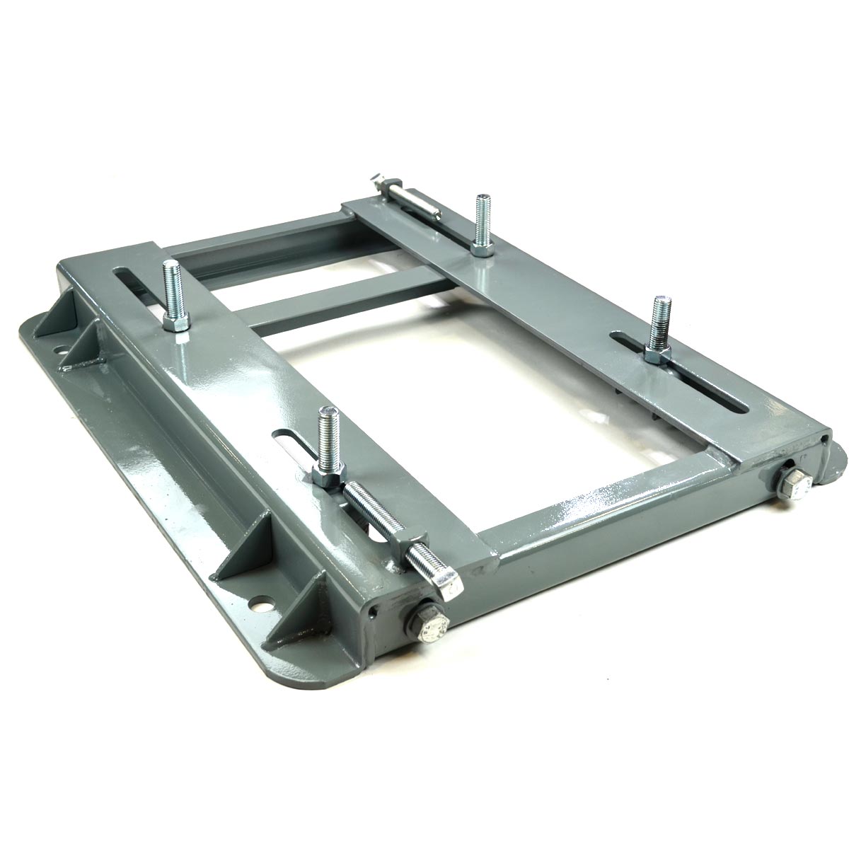
How does a motor base contribute to the stability and alignment of electric motors?
A motor base plays a crucial role in contributing to the stability and alignment of electric motors in industrial applications. Here’s a detailed explanation:
A motor base, also known as a motor mounting base or motor support base, provides essential support and alignment features that help ensure the stable and properly aligned positioning of electric motors. Here’s how a motor base contributes to stability and alignment:
1. Support and Weight Distribution: A motor base serves as a robust platform to support the weight of the electric motor. It helps distribute the motor’s weight evenly across the base, preventing excessive stress or strain on the motor and its mounting points. By providing adequate support, the motor base helps maintain the motor’s structural integrity and prevents any sagging or tilting that could lead to misalignment.
2. Adjustable Mounting Features: Motor bases often include adjustable features such as slotted holes or bolt patterns that allow for precise alignment of the motor. These adjustment options enable technicians to align the motor with connected equipment, such as pumps, fans, conveyors, or gearboxes. Proper alignment is crucial for efficient power transmission, minimizing wear and tear on the motor and connected components, and reducing the risk of mechanical failures.
3. Rigid Construction: Motor bases are typically constructed from sturdy materials like steel or cast iron, which provide rigidity and stability. The robust construction of the motor base helps absorb and dampen vibrations generated during motor operation, minimizing the transmission of vibrations to the surrounding equipment or structure. This vibration control contributes to the overall stability of the motor and its surrounding components.
4. Alignment Verification: Motor bases often include alignment verification features such as laser alignment systems or dial indicators. These tools assist technicians in precisely aligning the motor with connected equipment. By using these verification methods, technicians can ensure that the alignment is within specified tolerances, further enhancing stability and minimizing the risk of misalignment-related issues.
5. Secure Mounting: Motor bases are designed to securely attach the motor to the base, typically using bolts or fasteners. This secure mounting prevents any movement or shifting of the motor during operation, enhancing stability. It also helps maintain the alignment achieved during the installation process.
By providing support, adjustable alignment features, rigidity, alignment verification, and secure mounting, motor bases contribute significantly to the stability and alignment of electric motors in industrial applications. Proper stability and alignment are essential for optimal motor performance, reduced wear and tear, improved energy efficiency, and prolonged motor lifespan.
When installing a motor base, it’s crucial to follow manufacturer guidelines and ensure proper anchoring to the foundation or supporting structure. This helps maintain the integrity of the motor base and ensures the reliable operation of the motor.
In summary, a motor base is a critical component that contributes to the stability and alignment of electric motors by providing support, alignment adjustability, rigidity, alignment verification, and secure mounting, ultimately enhancing motor performance and reliability.
editor by CX 2023-11-17
China Best Sales Kk Series Motor Base and Flange vacuum pump ac system
Product Description
| KK60(Standard type) Specification | |||||||||
| Track length L2(mm) | Total length L1(mm) | Max.Strok | G(mm) | K(mm) | n | m | Weight(kg) | ||
| A1(Slide seat) | A2(Slide seat) | A1(Slide seat) | A2(Slide seat) | ||||||
| 150 | 220 | 60 | — | 25 | 100 | 2 | 2 | 1.5 | — |
| 200 | 270 | 110 | — | 50 | 100 | 2 | 2 | 1.8 | — |
| 300 | 370 | 210 | 135 | 50 | 200 | 3 | 2 | 2.4 | 2.7 |
| 400 | 470 | 310 | 235 | 50 | 100 | 4 | 4 | 3 | 3.3 |
| 500 | 570 | 410 | 335 | 50 | 200 | 5 | 3 | 3.6 | 3.9 |
| 600 | 670 | 510 | 435 | 50 | 100 | 6 | 6 | 4.2 | 4.6 |
Certifications
Packaging & Shipping
FAQ
Q1: Can your cylinders with HYVA ones ?
Yes, our cylinders can replace HYVA ones well, with same technical details and mounting sizes
Q2: What’s your cylinder’s advantages ?
The cylinders are made under strictly quality control processing.
All the raw materials and seals we used are all from world famous companies.
Cost effective
Q3: When your company be established ?
Our company be established in 1996, and we are professional for hydraulic cylinders for more than 25 years.
And we had passed IATF 16949:2016 Quality control system.
Q4: How about the delivery time ?
For samples about 20 days. And 15 to 30 days about mass orders.
Q5: How about the cylinder’s quality gurantee ?
We have 1 year quality grantee of the cylinders.
| Certification: | ISO9001, IATF 16949:2016 |
|---|---|
| Pressure: | Drive by Motor |
| Work Temperature: | Normal Temperature |
| Samples: |
US$ 500/Piece
1 Piece(Min.Order) | Order Sample |
|---|
| Customization: |
Available
|
|
|---|
.shipping-cost-tm .tm-status-off{background: none;padding:0;color: #1470cc}
|
Shipping Cost:
Estimated freight per unit. |
about shipping cost and estimated delivery time. |
|---|
| Payment Method: |
|
|---|---|
|
Initial Payment Full Payment |
| Currency: | US$ |
|---|
| Return&refunds: | You can apply for a refund up to 30 days after receipt of the products. |
|---|
How do motor bases contribute to ease of maintenance for electric motors?
Motor bases play a significant role in facilitating ease of maintenance for electric motors. Here’s a detailed explanation:
1. Accessibility: Motor bases provide easy access to the motor for maintenance purposes. They offer a stable and secure platform that allows technicians to reach the motor quickly and perform routine tasks such as inspection, cleaning, lubrication, and belt adjustments. Motor bases with open designs or removable covers further enhance accessibility by providing unobstructed access to critical motor components.
2. Adjustability: Many motor bases are adjustable, allowing for precise positioning and alignment of the motor. This adjustability simplifies maintenance procedures as it enables technicians to align the motor shaft with the driven equipment accurately. Proper alignment helps reduce wear, vibration, and energy loss, ultimately improving the motor’s performance and extending its lifespan.
3. Vibration Reduction: Motor bases often incorporate features that help dampen vibrations generated by the motor. Excessive vibrations can lead to premature wear and damage to both the motor and surrounding equipment. Motor bases equipped with vibration isolation pads or mounts absorb and dissipate vibrations, reducing stress on the motor and minimizing the need for frequent maintenance or repairs.
4. Easy Removal and Replacement: In some situations, it may be necessary to remove the motor from its base for more extensive maintenance or repairs. Motor bases are designed to facilitate the removal and replacement of motors as needed. They typically provide mounting features that allow for straightforward disconnection and reconnection of the motor, saving time and effort during maintenance activities.
5. Documentation and Labeling: Motor bases often include labeling or documentation areas where relevant information can be recorded. This documentation can include motor identification details, installation dates, maintenance schedules, and torque specifications. Having this information readily available on the motor base simplifies maintenance planning, tracking, and troubleshooting.
6. Compatibility with Accessories: Motor bases are often designed to be compatible with various accessories that aid in maintenance. These accessories may include cable management systems, drip pans for fluid containment, or mounting brackets for additional components. The compatibility of the motor base with such accessories enhances ease of maintenance by providing integrated solutions that support efficient and organized maintenance practices.
By incorporating these features and considerations, motor bases contribute to the ease of maintenance for electric motors. They provide accessibility, adjustability, vibration reduction, and easy removal options, simplifying routine maintenance tasks and ensuring the smooth operation and longevity of electric motors.
What role does corrosion resistance play in the selection of motor bases?
Corrosion resistance plays a crucial role in the selection of motor bases. Here’s a detailed explanation:
1. Protection of Motor Base: Motor bases are often exposed to various corrosive agents such as moisture, chemicals, saltwater, or industrial gases. Corrosion-resistant motor bases are designed to withstand these corrosive environments and prevent the deterioration of the base material. By selecting a corrosion-resistant motor base, you can ensure its durability and longevity, reducing the risk of premature failure or structural damage.
2. Preservation of Aesthetic and Functional Appearance: Corrosion can impact the aesthetic appearance of the motor base, causing discoloration, rust, or pitting. However, corrosion resistance helps maintain the visual appeal of the motor base over time. Additionally, corrosion can compromise the functionality of the motor base by weakening its structural integrity or hindering its adjustability features. By choosing a corrosion-resistant motor base, you can preserve both the aesthetic and functional aspects of the base.
3. Protection of Surrounding Equipment: Corrosion can extend beyond the motor base itself and affect other components or equipment in the vicinity. For example, if a corroded motor base transfers rust or contaminants to connected equipment, it can lead to operational issues or premature failure of those components. Opting for a corrosion-resistant motor base helps protect the surrounding equipment and ensures the smooth operation and reliability of the entire system.
4. Improved Maintenance Efficiency: Corrosion-resistant motor bases require less frequent maintenance and repair. They are less prone to degradation, which reduces the need for regular inspections, cleaning, and surface treatments. This not only saves time and effort but also minimizes maintenance costs associated with corrosion-related issues.
5. Environmental Compatibility: Industries or applications that involve exposure to corrosive environments, such as coastal areas, chemical plants, or wastewater treatment facilities, require motor bases that can withstand these conditions. Corrosion-resistant motor bases are designed to meet the specific environmental challenges and provide reliable performance in such demanding settings.
6. Long-Term Cost Savings: Although corrosion-resistant motor bases may have a higher initial cost compared to standard bases, they offer long-term cost savings. By investing in a high-quality corrosion-resistant motor base, you can mitigate the expenses associated with premature replacement, repairs, and downtime caused by corrosion-related issues.
When selecting a motor base, consider the environmental conditions, exposure to corrosive agents, and the expected service life of the motor base. Consult with manufacturers or suppliers to identify corrosion-resistant options that are compatible with the specific application requirements. They can provide guidance on suitable materials, coatings, or finishes that offer optimal corrosion resistance for your motor base.
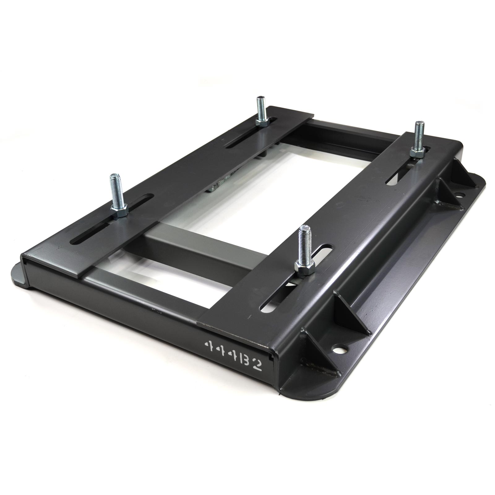
What is the purpose of a motor base in industrial applications?
A motor base serves an important purpose in industrial applications. Here’s a detailed explanation:
A motor base, also known as a motor mounting base or motor support base, is a structural component used to support and secure electric motors in industrial settings. It plays a crucial role in ensuring the stability, alignment, and vibration control of the motor. Here are some key purposes of a motor base:
1. Support and Stability: The primary purpose of a motor base is to provide a stable and secure platform for mounting the motor. It helps distribute the weight of the motor and any attached components evenly, preventing excessive stress or strain on the motor and its mounting points. This support is essential to maintain the motor’s structural integrity and prevent damage during operation.
2. Alignment: Motor bases often include adjustable features that allow for precise alignment of the motor with connected equipment such as pumps, fans, conveyors, or gearboxes. Proper alignment is critical for efficient power transmission, minimizing wear and tear on the motor and the connected equipment, and reducing the risk of mechanical failures.
3. Vibration Control: Vibrations can adversely affect the performance and lifespan of an electric motor. A motor base helps dampen and control vibrations generated during motor operation, reducing the transmission of vibrations to the surrounding equipment or structure. This helps minimize noise, prevents damage to nearby components, and enhances overall system reliability.
4. Maintenance and Serviceability: Motor bases are designed to facilitate maintenance and service tasks. They often feature accessibility features such as removable panels or brackets that allow technicians to easily access the motor for inspections, repairs, or replacements. Motor bases also simplify the process of disconnecting and reconnecting motors during maintenance activities.
5. Adaptability: Motor bases are available in various sizes, configurations, and materials to accommodate different motor types and installation requirements. They can be customized or equipped with modular components to adapt to specific applications or environmental conditions. This flexibility allows for easier installation and integration of motors into industrial systems.
Motor bases are typically made of sturdy materials like steel or cast iron to provide strength and durability. They are designed to withstand the dynamic forces, vibrations, and environmental conditions encountered in industrial environments.
When installing a motor base, it’s important to follow manufacturer guidelines and ensure proper anchoring to the foundation or supporting structure. This helps maintain the integrity of the motor base and ensures the reliable operation of the motor.
In summary, the purpose of a motor base in industrial applications is to provide support, stability, alignment, vibration control, and facilitate maintenance for electric motors, contributing to the overall performance, longevity, and reliability of the motor and the systems it powers.
editor by CX 2023-11-16
China OEM High Power Helical Single Phase AC Gear Motor with High Torque Long Life dc motor
Product Description
TaiBang Motor Industry Group Co., Ltd.
The main products is induction motor, reversible motor, DC brush gear motor, DC brushless gear motor, CH/CV big gear motors, Planetary gear motor ,Worm gear motor etc, which used widely in various fields of manufacturing pipelining, transportation, food, medicine, printing, fabric, packing, office, apparatus, entertainment etc, and is the preferred and matched product for automatic machine.
Motor Model Instruction
5RK40GN-CM
| 5 | R | K | 40 | R | GN | C | M |
| Frame Size | Type | Motor series | Power | Speed Control Motor |
Shaft Type | Voltage | Accessory |
| 2:60mm
3:70mm 4:80mm 5:90mm 6:104mm |
I:Induction
R:Reversible T:Torque |
K series | 6W
15W 25W 40W 60W 90W 120W 140W 180W 200W |
A:Round Shaft
GN:Bevel Gear Shaft GU:Bevel Gear Shaft |
A:Single Phase 110V
C:Single Phase 220V S:3-Phase 220V S3:3-Phase 380V S4:3-Phase 440V |
T/P:Thermally Protected
F:Fan M:Electro-magnetic |
Gear Head Model Instruction
5GN-100K
| 5 | GN | 100 | K | |
| Frame Size | Shaft Type | Gear Reduction Ratio | Bearing Type | Other information |
| 2:60mm
3:70mm 4:80mm 5:90mm 6:104mm |
GN:Bevel Gear Shaft (60#,70#,80#,90# reduction gear head) GU:Bevel Gear Shaft GM:Intermediate Gear Head GS:Gearhead with ears |
1:100 | K:Standard Rolling Bearing
RT:Right Angle With Axile RC:Right Angle With Hollow Shaft |
Sch as shaft diameter,shaft length,etc. |
Specification of motor 40W 90mm Fixed speed AC gear motor
| Type | Gear Tooth Output Shaft | Power (W) |
Frequency (Hz) |
Voltage (V) |
Current (A) |
Start Torque (g.cm) |
Rated | Gearbox Type | ||
| Torque (g.cm) |
Speed (rpm) |
Bearing Gearbox | Middle Gearbox | |||||||
| Reversible Motor | 5RK40GN-C | 40 | 50 | 220 | 0.45 | 3000 | 3000 | 1300 | 5GN/GU-K | 5GN10X |
| 40 | 60 | 220 | 0.41 | 2500 | 2515 | 1550 | 5GN/GU-K | 5GN10X | ||
Gear Head Torque Table(Kg.cm) (kg.cm×9.8÷100)=N.m
| Output Speed :RPM | 500 | 300 | 200 | 150 | 120 | 100 | 75 | 60 | 50 | 30 | 20 | 15 | 10 | 7.5 | 6 | 5 | 3 | ||
| Speed Ratio | 50Hz | 3 | 5 | 7.5 | 10 | 12.5 | 15 | 20 | 25 | 30 | 50 | 75 | 100 | 150 | 200 | 250 | 300 | 500 | |
| 60Hz | 3.6 | 6 | 9 | 15 | 18 | 30 | 36 | 60 | 90 | 120 | 180 | 300 | 360 | 600 | |||||
| Allowed Torque |
40W | kg.cm | 6.7 | 11 | 16 | 21.3 | 28 | 33 | 42 | 54 | 65 | 108 | 150 | 150 | 150 | 150 | 150 | 150 | 150 |
| 60W | kg.cm | 10 | 16 | 24 | 32 | 40 | 48 | 64 | 77 | 93 | 150 | 150 | 150 | 150 | 150 | 150 | 150 | 150 | |
| 90W | kg.cm | 14 | 23 | 35 | 46 | 58 | 69 | 92 | 110 | 133 | 200 | 200 | 200 | 200 | 200 | 200 | 200 | 200 | |
| 120W | kg.cm | 19 | 30.7 | 46 | 61 | 77 | 92 | 123 | 147 | 177 | 200 | 200 | 200 | 200 | 200 | 200 | 200 | 200 | |
| Note: Speed figures are based on synchronous speed, The actual output speed, under rated torque conditions, is about 10-20% less than synchronous speed, a grey background indicates output shaft of geared motor rotates in the same direction as output shaft of motor. A white background indicates rotates rotation in the opposite direction. | |||||||||||||||||||
Drawing:5RK40GN-C/5GN3~20K(Short gearbox shell 43mm)
Drawing:5RK40GN-C/5GN25~180K(Short gearbox shell 61mm)
Above drawing is for standard screw hole.If need through hole, terminal box, or electronic magnet brake, need to tell the seller.
Connection Diagram:
| Application: | Industrial |
|---|---|
| Speed: | Constant Speed |
| Number of Stator: | Single-Phase |
| Function: | Driving, Control |
| Casing Protection: | Closed Type |
| Number of Poles: | 4 |
| Samples: |
US$ 50/Piece
1 Piece(Min.Order) | |
|---|
| Customization: |
Available
| Customized Request |
|---|

The Benefits of Using a Gear Motor
A gear motor works on the principle of conservation of angular momentum. As the smaller gear covers more RPM and the larger gear produces more torque, the ratio between the two is greater than one. Similarly, a multiple gear motor follows the principle of energy conservation, with the direction of rotation always opposite to the one that is adjacent to it. It’s easy to understand the concept behind gear motors and the various types available. Read on to learn about the different types of gears and their applications.
Electric motor
The choice of an electric motor for gear motor is largely dependent on the application. There are various motor and gearhead combinations available, and some are more efficient than others. However, it is critical to understand the application requirements and select a motor that meets these needs. In this article, we’ll examine some of the benefits of using a gear motor. The pros and cons of each type are briefly discussed. You can buy new gear motors at competitive prices, but they aren’t the most reliable or durable option for your application.
To determine which motor is best for your application, you’ll need to consider the load and speed requirements. A gear motor’s efficiency (e) can be calculated by taking the input and output values and calculating their relation. On the graph below, the input (T) and output (P) values are represented as dashed lines. The input (I) value is represented as the torque applied to the motor shaft. The output (P) is the amount of mechanical energy converted. A DC gear motor is 70% efficient at 3.75 lb-in / 2,100 rpm.
In addition to the worm gear motor, you can also choose a compact DC worm gear motor with a variable gear ratio from 7.5 to 80. It has a range of options and can be custom-made for your specific application. The 3-phase AC gear motor, on the other hand, works at a rated power of one hp and torque of 1.143.2 kg-m. The output voltage is typically 220V.
Another important factor is the output shaft orientation. There are two main orientations for gearmotors: in-line and offset. In-line output shafts are most ideal for applications with high torque and short reduction ratios. If you want to avoid backlash, choose a right angle output shaft. An offset shaft can cause the output shaft to become excessively hot. If the output shaft is angled at a certain angle, it may be too large or too small.
Gear reducer
A gear reducer is a special kind of speed reducing motor, usually used in large machinery, such as compressors. These reducers have no cooling fan and are not designed to handle heavy loads. Different purposes require different service factors. For instance, a machine that requires frequent fast accelerations and occasional load spikes needs a gear reducer with a high service factor. A gear reducer that’s designed for long production shifts should be larger than a machine that uses it for short periods of time.
A gear reducer can reduce the speed of a motor by a factor of two. The reduction ratio changes the rotation speed of the receiving member. This change in speed is often required to solve problems of inertia mismatch. The torque density of a gear reducer is measured in newton meters and will depend on the motor used. The first criterion is the configuration of the input and output shafts. A gear ratio of 2:1, for example, means that the output speed has been cut in half.
Bevel gear reducers are a good option if the input and output shafts are perpendicular. This type is very robust and is perfect for situations where the angle between two axes is small. However, bevel gear reducers are expensive and require constant maintenance. They are usually used in heavy-duty conveyors and farm equipment. The correct choice of gear reducer for gear motor is crucial for the efficiency and reliability of the mechanism. To get the best gear reducer for your application, talk to a qualified manufacturer today.
Choosing a gear reducer for a gear motor can be tricky. The wrong one can ruin an entire machine, so it’s important to know the specifics. You must know the torque and speed requirements and choose a motor with the appropriate ratio. A gear reducer should also be compatible with the motor it’s intended for. In some cases, a smaller motor with a gear reducer will work better than a larger one.
Motor shaft
Proper alignment of the motor shaft can greatly improve the performance and life span of rotating devices. The proper alignment of motors and driven instruments enhances the transfer of energy from the motor to the instrument. Incorrect alignment leads to additional noise and vibration. It may also lead to premature failure of couplings and bearings. Misalignment also results in increased shaft and coupling temperatures. Hence, proper alignment is critical to improve the efficiency of the driven instrument.
When choosing the correct type of gear train for your motor, you need to consider its energy efficiency and the torque it can handle. A helical geared motor is more efficient for high output torque applications. Depending on the required speed and torque, you can choose between an in-line and a parallel helical geared motor. Both types of gears have their advantages and disadvantages. Spur gears are widespread. They are toothed and run parallel to the motor shaft.
A planetary gear motor can also have a linear output shaft. A stepping motor should not operate at too high current to prevent demagnetization, which will lead to step loss or torque drop. Ensure that the motor and gearbox output shafts are protected from external impacts. If the motor and gearbox are not protected against bumps, they may cause thread defects. Make sure that the motor shafts and rotors are protected from external impacts.
When choosing a metal for your gear motor’s motor shaft, you should consider the cost of hot-rolled bar stock. Its outer layers are more difficult to machine. This type of material contains residual stresses and other problems that make it difficult to machine. For these applications, you should choose a high-strength steel with hard outer layers. This type of steel is cheaper, but it also has size considerations. It’s best to test each material first to determine which one suits your needs.
In addition to reducing the speed of your device, a geared motor also minimizes the torque generated by your machine. It can be used with both AC and DC power. A high-quality gear motor is vital for stirring mechanisms and conveyor belts. However, you should choose a geared motor that uses high-grade gears and provides maximum efficiency. There are many types of planetary gear motors and gears on the market, and it’s important to choose the right one.
First stage gears
The first stage gears of a gear motor are the most important components of the entire device. The motor’s power transmission is 90% efficient, but there are many factors that can affect its performance. The gear ratios used should be high enough to handle the load, but not too high that they are limiting the motor’s speed. A gear motor should also have a healthy safety factor, and the lubricant must be sufficient to overcome any of these factors.
The transmission torque of the gear changes with its speed. The transmission torque at the input side of the gear decreases, transferring a small torque to the output side. The number of teeth and the pitch circle diameters can be used to calculate the torque. The first stage gears of gear motors can be categorized as spur gears, helical gears, or worm gears. These three types of gears have different torque capacities.
The first stage helical gear is the most important part of a gear motor. Its function is to transfer rotation from one gear to the other. Its output is the gearhead. The second stage gears are connected by a carrier. They work in tandem with the first stage gear to provide the output of the gearhead. Moreover, the first stage carrier rotates in the same direction as the input pinion.
Another important component is the output torque of the gearmotor. When choosing a gearmotor, consider the starting torque, running torque, output speed, overhung and shock loads, duty cycles, and more. It is crucial to choose a gearmotor with the right ratio for the application. By choosing the proper gearmotor, you will get maximum performance with minimal operating costs and increase plant productivity. For more information on first stage gears, check out our blog.
The first stage of a gear motor is composed of a set of fixed and rotating sprockets. The first stage of these gears acts as a drive gear. Its rotational mass is a limiting factor for torque. The second stage consists of a rotating shaft. This shaft rotates in the direction of the torque axis. It is also the limiting force for the motor’s torque.
editor by CX 2023-11-13
China best 3 Phase 60mm 80mmseries AC 100W 3000rpm Servo Motor with 90 Deg Planetary Gear Reducer for CNC Milling Machine with high quality
Product Description
80mm AC servo motor with Planetary Gearbo
Sepecification:
Details Images:
1. who are we?
We are based in ZheJiang , China, start from 2011,sell to Domestic Market(26.00%),Western Europe(20.00%),North
America(20.00%),Northern Europe(10.00%),Eastern Europe(7.00%),Africa(5.00%),Southeast Asia(5.00%),Mid East(5.00%),South America(2.00%). There are total about 51-100 people in our office.
2. how can we guarantee quality?
We are based in ZheJiang , China, start from 2011,sell to Domestic Market(26.00%),Western Europe(20.00%),North
America(20.00%),Northern Europe(10.00%),Eastern Europe(7.00%),Africa(5.00%),Southeast Asia(5.00%),Mid East(5.00%),South America(2.00%). There are total about 51-100 people in our office.
3.what can you buy from us?
Always a pre-production sample before mass production;
Always final Inspection before shipment;
4. why should you buy from us not from other suppliers?
Professional one-to-1 motor customized . The world’s large enterprise of choice for high quality suppliers . ISO9001:2008 quality management system certification, through the CE, ROHS certification.
5. what services can we provide?
Accepted Delivery Terms: FOB,CFR,CIF,EXW,CIP,FCA,CPT,DDP,DDU,Express Delivery,DAF,DES;
Accepted Payment Currency:USD,EUR,CAD,HKD,GBP,CNY;
Accepted Payment Type: T/T,L/C,D/P D/A,MoneyGram,Credit Card,PayPal,Western Union,Cash,Escrow;
Language Spoken:English,Chinese
| Speed: | Low Speed |
|---|---|
| Function: | Control |
| Certification: | ISO9001, CE RoHS |
| Brand: | Jkongmotor |
| Transport Package: | Export Carton |
| Origin: | China |
| Samples: |
US$ 320/Piece
1 Piece(Min.Order) | |
|---|
| Customization: |
Available
| Customized Request |
|---|
Benefits of a Planetary Motor
Besides being one of the most efficient forms of a drive, a Planetary Motor also offers a great number of other benefits. These features enable it to create a vast range of gear reductions, as well as generate higher torques and torque density. Let’s take a closer look at the benefits this mechanism has to offer. To understand what makes it so appealing, we’ll explore the different types of planetary systems.
Solar gear
The solar gear on a planetary motor has two distinct advantages. It produces less noise and heat than a helical gear. Its compact footprint also minimizes noise. It can operate at high speeds without sacrificing efficiency. However, it must be maintained with constant care to operate efficiently. Solar gears can be easily damaged by water and other debris. Solar gears on planetary motors may need to be replaced over time.
A planetary gearbox is composed of a sun gear and two or more planetary ring and spur gears. The sun gear is the primary gear and is driven by the input shaft. The other two gears mesh with the sun gear and engage the stationary ring gear. The three gears are held together by a carrier, which sets the spacing. The output shaft then turns the planetary gears. This creates an output shaft that rotates.
Another advantage of planetary gears is that they can transfer higher torques while being compact. These advantages have led to the creation of solar gears. They can reduce the amount of energy consumed and produce more power. They also provide a longer service life. They are an excellent choice for solar-powered vehicles. But they must be installed by a certified solar energy company. And there are other advantages as well. When you install a solar gear on a planetary motor, the energy produced by the sun will be converted to useful energy.
A solar gear on a planetary motor uses a solar gear to transmit torque from the sun to the planet. This system works on the principle that the sun gear rotates at the same rate as the planet gears. The sun gear has a common design modulus of -Ns/Np. Hence, a 24-tooth sun gear equals a 3-1/2 planet gear ratio. When you consider the efficiency of solar gears on planetary motors, you will be able to determine whether the solar gears are more efficient.
Sun gear
The mechanical arrangement of a planetary motor comprises of two components: a ring gear and a sun gear. The ring gear is fixed to the motor’s output shaft, while the sun gear rolls around and orbits around it. The ring gear and sun gear are linked by a planetary carrier, and the torque they produce is distributed across their teeth. The planetary structure arrangement also reduces backlash, and is critical to achieve a quick start and stop cycle.
When the two planetary gears rotate independently, the sun gear will rotate counterclockwise and the ring-gear will turn in the same direction. The ring-gear assembly is mounted in a carrier. The carrier gear and sun gear are connected to each other by a shaft. The planetary gears and sun gear rotate around each other on the ring-gear carrier to reduce the speed of the output shaft. The planetary gear system can be multiplied or staged to obtain a higher reduction ratio.
A planetary gear motor mimics the planetary rotation system. The input shaft turns a central gear, known as the sun gear, while the planetary gears rotate around a stationary sun gear. The motor’s compact design allows it to be easily mounted to a vehicle, and its low weight makes it ideal for small vehicles. In addition to being highly efficient, a planetary gear motor also offers many other benefits.
A planetary gearbox uses a sun gear to provide torque to the other gears. The planet pinions mesh with an internal tooth ring gear to generate rotation. The carrier also acts as a hub between the input gear and output shaft. The output shaft combines these two components, giving a higher torque. There are three types of planetary gearboxes: the sun gear and a wheel drive planetary gearbox.
Planetary gear
A planetary motor gear works by distributing rotational force along a separating plate and a cylindrical shaft. A shock-absorbing device is included between the separating plate and cylindrical shaft. This depressed portion prevents abrasion wear and foreign particles from entering the device. The separating plate and shaft are positioned coaxially. In this arrangement, the input shaft and output shaft are rotated relative to one another. The rotatable disc absorbs the impact.
Another benefit of a planetary motor gear is its efficiency. Planetary motor gears are highly efficient at transferring power, with 97% of the input energy being transferred to the output. They can also have high gear ratios, and offer low noise and backlash. This design also allows the planetary gearbox to work with electric motors. In addition, planetary gears also have a long service life. The efficiency of planetary gears is due in part to the large number of teeth.
Other benefits of a planetary motor gear include the ease of changing ratios, as well as the reduced safety stock. Unlike other gears, planetary gears don’t require special tools for changing ratios. They are used in numerous industries, and share parts across multiple sizes. This means that they are cost-effective to produce and require less safety stock. They can withstand high shock and wear, and are also compact. If you’re looking for a planetary motor gear, you’ve come to the right place.
The axial end surface of a planetary gear can be worn down by abrasion with a separating plate. In addition, foreign particles may enter the planetary gear device. These particles can damage the gears or even cause noise. As a result, you should check planetary gears for damage and wear. If you’re looking for a gear, make sure it has been thoroughly tested and installed by a professional.
Planetary gearbox
A planetary motor and gearbox are a common combination of electric and mechanical power sources. They share the load of rotation between multiple gear teeth to increase the torque capacity. This design is also more rigid, with low backlash that can be as low as one or two arc minutes. The advantages of a planetary gearmotor over a conventional electric motor include compact size, high efficiency, and less risk of gear failure. Planetary gear motors are also more reliable and durable than conventional electric motors.
A planetary gearbox is designed for a single stage of reduction, or a multiple-stage unit can be built with several individual cartridges. Gear ratios may also be selected according to user preference, either to face mount the output stage or to use a 5mm hex shaft. For multi-stage planetary gearboxes, there are a variety of different options available. These include high-efficiency planetary gearboxes that achieve a 98% efficiency at single reduction. In addition, they are noiseless, and reduce heat loss.
A planetary gearbox may be used to increase torque in a robot or other automated system. There are different types of planetary gear sets available, including gearboxes with sliding or rolling sections. When choosing a planetary gearset, consider the environment and other factors such as backlash, torque, and ratio. There are many advantages to a planetary gearbox and the benefits and drawbacks associated with it.
Planetary gearboxes are similar to those in a solar system. They feature a central sun gear in the middle, two or more outer gears, and a ring gear at the output. The planetary gears rotate in a ring-like structure around a stationary sun gear. When the gears are engaged, they are connected by a carrier that is fixed to the machine’s shaft.
Planetary gear motor
Planetary gear motors reduce the rotational speed of an armature by one or more times. The reduction ratio depends on the structure of the planetary gear device. The planetary gear device has an output shaft and an armature shaft. A separating plate separates the two. The output shaft moves in a circular pattern to turn the pinion 3. When the pinion rotates to the engagement position, it is engaged with the ring gear 4. The ring gear then transmits the rotational torque to the armature shaft. The result is that the engine cranks up.
Planetary gear motors are cylindrical in shape and are available in various power levels. They are typically made of steel or brass and contain multiple gears that share the load. These motors can handle massive power transfers. The planetary gear drive, on the other hand, requires more components, such as a sun’s gear and multiple planetary gears. Consequently, it may not be suitable for all types of applications. Therefore, the planetary gear drive is generally used for more complex machines.
Brush dusts from the electric motor may enter the planetary gear device and cause it to malfunction. In addition, abrasion wear on the separating plate can affect the gear engagement of the planetary gear device. If this occurs, the gears will not engage properly and may make noise. In order to prevent such a situation from occurring, it is important to regularly inspect planetary gear motors and their abrasion-resistant separating plates.
Planetary gear motors come in many different power levels and sizes. These motors are usually cylindrical in shape and are made of steel, brass, plastic, or a combination of both materials. A planetary gear motor can be used in applications where space is an issue. This motor also allows for low gearings in small spaces. The planetary gearing allows for large amounts of power transfer. The output shaft size is dependent on the gear ratio and the motor speed.
editor by CX 2023-04-18
China YN70-20 AC motor with speed reduce gearbox 70JB30G10 with Great quality
Guarantee: 3months-1year
Model Amount: YN70-20
Type: Reversible Motor
Frequency: 50HZ, fifty Hz
Stage: Solitary-stage
Shield Attribute: Drip-evidence
AC Voltage: 208-230 / 240 V
Effectiveness: IE 1
Electrical power: 20W
Voltage: 220V
No. of Pole: 4 poles
Recent: .25A
Starting Torque: a hundred and seventy mN.m
Rated Torque: a hundred and sixty mN.m
Rated Pace: 1200 r/min
Capacitor: 1.8/450
Speed reducer: 70JB30G10
Packaging Specifics: Regular Robust Export Carton Box According To Your Needs
YN70-twenty AC motor with velocity decrease gearbox 70JB30G10Reducer gear is combine gear box and motor. This built-in body would typically be called a gear motor or equipment motor.1, gear motor with worldwide technical specifications for production, higher engineering articles.2, place-saving, reliable and tough, endure high overload potential, electrical power up to 95KW or more.3, minimal energy use, exceptional functionality, velocity reducer performance up to 95%.4, small vibration, reduced sounds, vitality, substantial-good quality solid metal, steel forged iron box, equipment floor after HF remedy.5, precision machining, to guarantee parallel shaft and positioning precision, 6 grooves massive pulley wheel metal material for gearbox pulley all this constitutes a equipment generate equipment motor assembly configured different kinds of motor, forming a mechanical and electrical integration, totally confirmed item good quality attributes.6, the solution makes use of a collection, modular layout, a vast assortment of adaptability, this series has an very multi-motor mix, mounting placement and construction of the system, in accordance to the actual require to choose any pace and a variety of structural kinds. Relevant Merchandise Reliable shaft variety GHS38 Collection.Widely employed in automated control, automatic measurement, as the angle and speed sensors.
ASIC products internal, very good reliability, long lifestyle, anti-jamming overall performance. Stainless steel shaft has a higher balance and security.Steel shell is more reliable and anti-influence. Bearing load weighty, anti-oil and water
Servo-motor Encoder GSM48 Series.Widely utilised in the field of automatic handle AC servo device, particularly suited for use in servo motor supporting.
Internal ASIC products, higher trustworthiness, lengthy daily life, powerful anti-interference. Broad variety of resolutions, 42mm 24V 72v 3kw BLDC Brushless DC Motor 105W 4000RPM with Controller Diver Long lasting Magnet equipment Motor package lower pace hair dryer and does not call for signal conditioning. With A, B, Z and U, V, W six-channel sign output can be connected with standard line driver (26LS31) RS422, can provide twelve output signal, and is suitable with TTL
Hollow Shaft Variety GHH38 Series.Used in automated management, measurement, robotic X-Y working system, printing and packaging.Internal ASIC products, large reliability, extended daily life, strong anti-interference. much more sound metallic housing could anti-shock. Outlet finish steel interface sets of water-resistant safety.
Hollow Shaft Kind GHH100 sequence.Used in automatic control, measurement, robot X-Y doing work platform, printing and packaging.Interior ASIC products, higher dependability, prolonged daily life, strong anti-interference. far more sound metal housing could anti-shock. Outlet finish metal interface sets of waterproof security.
Handbook Pulse Generator TM1469 collection.For CNC device origin correction and signal split.
Complete plastic housing, TT Motor Pace Reducer Gearbox Substantial Torque Electric Dc Motor For Coffee Grinder high dielectric toughness, the axis transfer switch and Oil Pollution Avoidance seal design.
Attract-wire Placement Sensor CESI collection.compact measurement, rugged design, straightforward to set up
economic price, and expense cost savings for customersVarious signals output optional: drive-pull, TTL, open collector and so on
The cylinders, screening equipment and other business has reached massive-scale programs, dependability
Our Manufacturing facility Packing & Shipping Packing Particulars : carton packed for each and every reducer or things, and then pack with thick carton for shipping.
Delivery Details : 3-4 times after entire payment in standard solution, and 7-10days for tailored type. and in accordance to quantities.
one. Ziplock packed two. Box Packing 3. Packed with excellent circumstances with transport mark. Welcome To Manufacturing unit FAQ Q: Are you trading organization or manufacturer ?A: We are factory.
Q: How prolonged is your shipping time?A: Usually it is 5-8 days if the merchandise are in stock. or it is ten-fifteen days if the merchandise are not in inventory, it is according to amount.
Q: Do you offer samples ? is it cost-free or added ?A: Yes, we could offer the sample but do not spend the value of freight.
Q: What is your phrases of payment ?A: Payment=10000USD, 30% T/T in progress ,harmony prior to shippment.
SERVICE:
ON LINE Chatting OR Deliver YOUR Ask for BY E mail Immediately. WE WILL REPLY YOU Inside 24 Hours.
The Basics of a Gear Motor
The basic mechanism behind the gear motor is the principle of conservation of angular momentum. The smaller the gear, the more RPM it covers and the larger the gear, the more torque it produces. The ratio of angular velocity of two gears is called the gear ratio. Moreover, the same principle applies to multiple gears. This means that the direction of rotation of each adjacent gear is always the opposite of the one it is attached to.
Induction worm gear motor
If you’re looking for an electric motor that can deliver high torque, an Induction worm gear motor might be the right choice. This type of motor utilizes a worm gear attached to the motor to rotate a main gear. Because this type of motor is more efficient than other types of motors, it can be used in applications requiring massive reduction ratios, as it is able to provide more torque at a lower speed.
The worm gear motor is designed with a spiral shaft that is set into splines in another gear. The speed at which the worm gear rotates is dependent on the torque produced by the main gear. Induction worm gear motors are best suited for use in low-voltage applications such as electric cars, renewable energy systems, and industrial equipment. They come with a wide range of power-supply options, including twelve-volt, 24-volt, and 36-volt AC power supplies.
These types of motors can be used in many industrial settings, including elevators, airport equipment, food packaging facilities, and more. They also produce less noise than other types of motors, which makes them a popular choice for manufacturers with limited space. The efficiency of worm gearmotors makes them an excellent choice for applications where noise is an issue. Induction worm gear motors can be compact and extremely high-torque.
While the Induction worm gear motor is most widely used in industrial applications, there are other kinds of gearmotors available. Some types are more efficient than others, and some are more expensive than others. For your application, choosing the correct motor and gearbox combination is crucial to achieving the desired result. You’ll find that the Induction worm gear motor is an excellent choice for many applications. The benefits of an Induction worm gear motor can’t be overstated.
The DC gear motor is an excellent choice for high-end industrial applications. This type of gearmotor is smaller and lighter than a standard AC motor and can deliver up to 200 watts of torque. A gear ratio of three to two can be found in these motors, which makes them ideal for a wide range of applications. A high-quality DC gear motor is a great choice for many industrial applications, as they can be highly efficient and provide a high level of reliability.
Electric gear motors are a versatile and widely used type of electric motor. Nevertheless, there are some applications that don’t benefit from them, such as applications with high shaft speed and low torque. Applications such as fan motors, pump and scanning machines are examples of such high-speed and high-torque demands. The most important consideration when choosing a gearmotor is its efficiency. Choosing the right size will ensure the motor runs efficiently at peak efficiency and will last for years.
Parallel shaft helical gear motor
The FC series parallel shaft helical gearmotor is a compact, lightweight, and high-performance unit that utilizes a parallel shaft structure. Its compact design is complemented by high transmission efficiency and high carrying capacity. The motor’s material is 20CrMnTi alloy steel. The unit comes with either a flanged input or bolt-on feet for installation. Its low noise and compact design make it an ideal choice for a variety of applications.
The helical gears are usually arranged in two rows of one another. Each row contains one or more rows of teeth. The parallel row has the teeth in a helical pattern, while the helical rows are lined up parallelly. In addition to this, the cross helical gears have a point contact design and do not overlap. They can be either parallel or crossed. The helical gear motors can have any number of helical pairs, each with a different pitch circle diameter.
The benefits of the Parallel Shaft Helical Gearbox include high temperature and pressure handling. It is produced by skilled professionals using cutting-edge technology, and is widely recognized for its high performance. It is available in a range of technical specifications and is custom-made to suit individual requirements. These gearboxes are durable and low-noise and feature high reliability. You can expect to save up to 40% of your energy by using them.
The parallel shaft helical gear motors are designed to reduce the speed of a rotating part. The nodular cast iron housing helps make the unit robust in difficult environments, while the precision-machined gears provide quiet, vibration-free operation. These motors are available in double reduction, triple reduction, and quadruple reduction. The capacity ranges from 0.12 kW to 45 kW. You can choose from a wide variety of capacities, depending on the size of your gearing needs.
The SEW-EURODRIVE parallel shaft helical gearmotor is a convenient solution for space-constrained applications. The machine’s modular design allows for easy mounting and a wide range of ambient temperatures. They are ideal for a variety of mechanical applications, including conveyors, augers, and more. If you want a small footprint, the SEW-EURODRIVE parallel shaft helical gear motor is the best solution for you.
The parallel shaft helical gears are advantageous for both high and low speed applications. Parallel helical gears are also suitable for low speed and low duty applications. A good example of a cross-helix gear is the oil pump of an internal combustion engine. Both types of helical gears are highly reliable and offer vibration-free operation. They are more costly than conventional gear motors, but offer more durability and efficiency.
Helical gear unit
This helical gear unit is designed to operate under a variety of demanding conditions and can be used in a wide range of applications. Designed for long life and high torque density, this gear unit is available in a variety of torques and gear ratios. Its design and construction make it compatible with a wide range of critical mechanical systems. Common applications include conveyors, material handling, steel mills, and paper mills.
Designed for high-performance applications, the Heidrive helical gear unit provides superior performance and value. Its innovative design allows it to function well under a wide range of operating conditions and is highly resistant to damage. These gear motors can be easily combined with a helical gear unit. Their combined power output is 100 Nm, and they have a high efficiency of up to 90%. For more information about the helical gear motor, contact a Heidrive representative.
A helical gear unit can be classified by its reference section in the standard plane or the turning plane. Its center gap is the same as that of a spur gear, and its number of teeth is the same. In addition to this, the helical gear has a low axial thrust, which is another important characteristic. The helical gear unit is more efficient at transferring torque than a spur gear, and it is quieter, too.
These units are designed to handle large loads. Whether you are using them for conveyors, augers, or for any other application that involves high-speed motion, a helical gear unit will deliver maximum performance. A helical gear unit from Flender can handle 400,000 tasks with a high degree of reliability. Its high efficiency and high resistance to load ensures high plant availability. These gear motors are available in a variety of sizes, from single-speed to multi-speed.
PEC geared motors benefit from decades of design experience and high quality materials. They are robust, quiet, and offer excellent performance. They are available in multiple configurations and are dimensionally interchangeable with other major brands. The gear motors are manufactured as modular kits to minimize inventory. They can be fitted with additional components, such as backstops and fans. This makes it easy to customize your gear motors and save money while reducing costs.
Another type of helical gears is the double helical gear. The double helical gear unit has two helical faces with a gap between them. They are better for enclosed gear systems as they provide greater tooth overlap and smoother performance. Compared to double helical gears, they are smaller and more flexible than the Herringbone type. So, if you’re looking for a gear motor, a helical gear unit may be perfect for you.
editor by czh 2023-02-21
China OMRON AC servo motor R88M-K1K030F-S2 big stock motor armature
Guarantee: 1 year
Design Variety: R88M-K1K030F-S2
Variety: SERVO MOTOR
Frequency: 250Hz
Section: Single-period
Safeguard Characteristic: Watertight
AC Voltage: one hundred fifteen/one hundred twenty V
Effectiveness: IE 1
Use: Placement Sensor
Packaging Specifics: Regular Sturdy Export Carton Box In accordance To Your Requirements
OMRON AC servo motor R88M-K1K030F-S2 massive inventory Merchandise Demonstrate Relevant merchandise GHS5208 Sequence Sound-Shaft Incremental Rotary Encoder
GHH80 Series Hollow-Shaft Incremental Rotary Encoder
CESI-S1000 attract wire linear situation sensor
CAS60 Absolute Rotary encoder
PD30 collection incremental rotary encoder kit Utilize to DC motor
TM1474 Collection Manual Wheel Pulse Generator Utilize to CNC
Our Firm ZheJiang Qiyi Electrical & Mechanical Gear Co., Ltd. is a skilled rotary encoder provider, positioned in Chinese company and port middle, ZheJiang . CALT manufacturer solution ranges: Optical incremental rotary encoder, solitary-turn and multi-change absolute encoder, High good quality black or zinc galvanized set screw and clamp 10mm shaft collar and solitary break up shaft collar draw-wire place sensor and couplings, and other instruments, which broadly employed in CNC equipment, textile machinery, steel rolling equipment, linear CZPT method, 5 grooves C belt elevator push pulley cone pulley for QD bushings hydraulic system, lifting equipment and servo motor, all get a quite great track record! Qiyi organization has got independent import and export qualification in 2013, CALT manufacturer goods have been exported to Southeast Asia, Europe, Electric Vehicle Areas 24V 110A CZPT Everlasting Magnet DC Motor Velocity Controller 1228-2908 America and Russia and other nations around the world and regions in the world.
Manufacturing facility Building9# 302, No. 4361 CZPT Street, HangZhou District, ZheJiang
Screening MachineOscilloscope
Screening MachineIndustrial microscope
Testing MachinePlug and dial
warehouse: widespread variety rotary encoders are all in stock can ship our in 2-3 days.
warehouse
warehouse
Certifications Packing & Shipping and delivery Packing Specifics : carton packed for each encoder or objects, and then pack with thick carton for shipping.
Shipping and delivery Information : 2-3 times following total payment in standard item, 17 Inch 3000W 72V Fast Pace Electrical Brushless Dc Motor For Bike and 3-7 days for personalized type. and according to quantities.
1. Rotary encoder pack box 2 levels. two. All packed good three. Encoder module disc in plastic box 4. Ziplock packed for flexible coupling 5. Rotary encoder packed properly six. Packed with excellent problems with shipping and delivery mark.
Dynamic Modeling of a Planetary Motor
A planetary gear motor consists of a series of gears rotating in perfect synchrony, allowing them to deliver torque in a higher output capacity than a spur gear motor. Unlike the planetary motor, spur gear motors are simpler to build and cost less, but they are better for applications requiring lower torque output. That is because each gear carries the entire load. The following are some key differences between the two types of gearmotors.
planetary gear system
A planetary gear transmission is a type of gear mechanism that transfers torque from one source to another, usually a rotary motion. Moreover, this type of gear transmission requires dynamic modeling to investigate its durability and reliability. Previous studies included both uncoupled and coupled meshing models for the analysis of planetary gear transmission. The combined model considers both the shaft structural stiffness and the bearing support stiffness. In some applications, the flexible planetary gear may affect the dynamic response of the system.
In a planetary gear device, the axial end surface of the cylindrical portion is rotatable relative to the separating plate. This mechanism retains lubricant. It is also capable of preventing foreign particles from entering the planetary gear system. A planetary gear device is a great choice if your planetary motor’s speed is high. A high-quality planetary gear system can provide a superior performance than conventional systems.
A planetary gear system is a complex mechanism, involving three moving links that are connected to each other through joints. The sun gear acts as an input and the planet gears act as outputs. They rotate about their axes at a ratio determined by the number of teeth on each gear. The sun gear has 24 teeth, while the planet gears have three-quarters that ratio. This ratio makes a planetary motor extremely efficient.
planetary gear train
To predict the free vibration response of a planetary motor gear train, it is essential to develop a mathematical model for the system. Previously, static and dynamic models were used to study the behavior of planetary motor gear trains. In this study, a dynamic model was developed to investigate the effects of key design parameters on the vibratory response. Key parameters for planetary gear transmissions include the structure stiffness and mesh stiffness, and the mass and location of the shaft and bearing supports.
The design of the planetary motor gear train consists of several stages that can run with variable input speeds. The design of the gear train enables the transmission of high torques by dividing the load across multiple planetary gears. In addition, the planetary gear train has multiple teeth which mesh simultaneously in operation. This design also allows for higher efficiency and transmittable torque. Here are some other advantages of planetary motor gear trains. All these advantages make planetary motor gear trains one of the most popular types of planetary motors.
The compact footprint of planetary gears allows for excellent heat dissipation. High speeds and sustained performances will require lubrication. This lubricant can also reduce noise and vibration. But if these characteristics are not desirable for your application, you can choose a different gear type. Alternatively, if you want to maintain high performance, a planetary motor gear train will be the best choice. So, what are the advantages of planetary motor gears?
planetary gear train with fixed carrier train ratio
The planetary gear train is a common type of transmission in various machines. Its main advantages are high efficiency, compactness, large transmission ratio, and power-to-weight ratio. This type of gear train is a combination of spur gears, single-helical gears, and herringbone gears. Herringbone planetary gears have lower axial force and high load carrying capacity. Herringbone planetary gears are commonly used in heavy machinery and transmissions of large vehicles.
To use a planetary gear train with a fixed carrier train ratio, the first and second planets must be in a carrier position. The first planet is rotated so that its teeth mesh with the sun’s. The second planet, however, cannot rotate. It must be in a carrier position so that it can mesh with the sun. This requires a high degree of precision, so the planetary gear train is usually made of multiple sets. A little analysis will simplify this design.
The planetary gear train is made up of three components. The outer ring gear is supported by a ring gear. Each gear is positioned at a specific angle relative to one another. This allows the gears to rotate at a fixed rate while transferring the motion. This design is also popular in bicycles and other small vehicles. If the planetary gear train has several stages, multiple ring gears may be shared. A stationary ring gear is also used in pencil sharpener mechanisms. Planet gears are extended into cylindrical cutters. The ring gear is stationary and the planet gears rotate around a sun axis. In the case of this design, the outer ring gear will have a -3/2 planet gear ratio.
planetary gear train with zero helix angle
The torque distribution in a planetary gear is skewed, and this will drastically reduce the load carrying capacity of a needle bearing, and therefore the life of the bearing. To better understand how this can affect a gear train, we will examine two studies conducted on the load distribution of a planetary gear with a zero helix angle. The first study was done with a highly specialized program from the bearing manufacturer INA/FAG. The red line represents the load distribution along a needle roller in a zero helix gear, while the green line corresponds to the same distribution of loads in a 15 degree helix angle gear.
Another method for determining a gear’s helix angle is to consider the ratio of the sun and planet gears. While the sun gear is normally on the input side, the planet gears are on the output side. The sun gear is stationary. The two gears are in engagement with a ring gear that rotates 45 degrees clockwise. Both gears are attached to pins that support the planet gears. In the figure below, you can see the tangential and axial gear mesh forces on a planetary gear train.
Another method used for calculating power loss in a planetary gear train is the use of an auto transmission. This type of gear provides balanced performance in both power efficiency and load capacity. Despite the complexities, this method provides a more accurate analysis of how the helix angle affects power loss in a planetary gear train. If you’re interested in reducing the power loss of a planetary gear train, read on!
planetary gear train with spur gears
A planetary gearset is a type of mechanical drive system that uses spur gears that move in opposite directions within a plane. Spur gears are one of the more basic types of gears, as they don’t require any specialty cuts or angles to work. Instead, spur gears use a complex tooth shape to determine where the teeth will make contact. This in turn, will determine the amount of power, torque, and speed they can produce.
A two-stage planetary gear train with spur gears is also possible to run at variable input speeds. For such a setup, a mathematical model of the gear train is developed. Simulation of the dynamic behaviour highlights the non-stationary effects, and the results are in good agreement with the experimental data. As the ratio of spur gears to spur gears is not constant, it is called a dedendum.
A planetary gear train with spur gears is a type of epicyclic gear train. In this case, spur gears run between gears that contain both internal and external teeth. The circumferential motion of the spur gears is analogous to the rotation of planets in the solar system. There are four main components of a planetary gear train. The planet gear is positioned inside the sun gear and rotates to transfer motion to the sun gear. The planet gears are mounted on a joint carrier that is connected to the output shaft.
planetary gear train with helical gears
A planetary gear train with helical teeth is an extremely powerful transmission system that can provide high levels of power density. Helical gears are used to increase efficiency by providing a more efficient alternative to conventional worm gears. This type of transmission has the potential to improve the overall performance of a system, and its benefits extend far beyond the power density. But what makes this transmission system so appealing? What are the key factors to consider when designing this type of transmission system?
The most basic planetary train consists of the sun gear, planet gear, and ring gear elements. The number of planets varies, but the basic structure of planetary gears is similar. A simple planetary geartrain has the sun gear driving a carrier assembly. The number of planets can be as low as two or as high as six. A planetary gear train has a low mass inertia and is compact and reliable.
The mesh phase properties of a planetary gear train are particularly important in designing the profiles. Various parameters such as mesh phase difference and tooth profile modifications must be studied in depth in order to fully understand the dynamic characteristics of a PGT. These factors, together with others, determine the helical gears’ performance. It is therefore essential to understand the mesh phase of a planetary gear train to design it effectively.
editor by czh 2023-02-20
China Japan MHMD082Q1U MCDHT3520E 0.75kw1.5KW AC servo motor pet injection macheen china panasonic servo motor and Driver with Hot selling
Guarantee: 1 calendar year
Design Quantity: Panasonic
Sort: SERVO MOTOR, High Voltage Motor
Frequency: 50/60hz
Section: 3-period
Safeguard Feature: Totally Enclosed
AC Voltage: 110-460v
Efficiency: Ie three
Item Identify: servo motor
Use: Machinery Tools
Defense course: IP45/IP54/IP55/IP67/IP77
Condition: a hundred% Unique Brand name
Port: HangZhou
Specification
| item | value |
| Warranty | 1 yr |
| Place of Origin | Japan |
| Brand Title | panasonic |
| Model Variety | Panasonic |
| Type | SERVO MOTOR |
| Frequency | 50/60hz |
| Phase | Three-stage |
| Protect Characteristic | Totally Enclosed |
| AC Voltage | 110-460v |
| Efficiency | Ie three |
| Product Title | servo motor |
| Type | High Voltage Motor |
| Usage | Machinery Tools |
| Protection course | IP45/IP54/IP55/IP67/IP77 |
| Condition | 100% Authentic Brand name |
Dynamic Modeling of a Planetary Motor
A planetary gear motor consists of a series of gears rotating in perfect synchrony, allowing them to deliver torque in a higher output capacity than a spur gear motor. Unlike the planetary motor, spur gear motors are simpler to build and cost less, but they are better for applications requiring lower torque output. That is because each gear carries the entire load. The following are some key differences between the two types of gearmotors.
planetary gear system
A planetary gear transmission is a type of gear mechanism that transfers torque from one source to another, usually a rotary motion. Moreover, this type of gear transmission requires dynamic modeling to investigate its durability and reliability. Previous studies included both uncoupled and coupled meshing models for the analysis of planetary gear transmission. The combined model considers both the shaft structural stiffness and the bearing support stiffness. In some applications, the flexible planetary gear may affect the dynamic response of the system.
In a planetary gear device, the axial end surface of the cylindrical portion is rotatable relative to the separating plate. This mechanism retains lubricant. It is also capable of preventing foreign particles from entering the planetary gear system. A planetary gear device is a great choice if your planetary motor’s speed is high. A high-quality planetary gear system can provide a superior performance than conventional systems.
A planetary gear system is a complex mechanism, involving three moving links that are connected to each other through joints. The sun gear acts as an input and the planet gears act as outputs. They rotate about their axes at a ratio determined by the number of teeth on each gear. The sun gear has 24 teeth, while the planet gears have three-quarters that ratio. This ratio makes a planetary motor extremely efficient.
planetary gear train
To predict the free vibration response of a planetary motor gear train, it is essential to develop a mathematical model for the system. Previously, static and dynamic models were used to study the behavior of planetary motor gear trains. In this study, a dynamic model was developed to investigate the effects of key design parameters on the vibratory response. Key parameters for planetary gear transmissions include the structure stiffness and mesh stiffness, and the mass and location of the shaft and bearing supports.
The design of the planetary motor gear train consists of several stages that can run with variable input speeds. The design of the gear train enables the transmission of high torques by dividing the load across multiple planetary gears. In addition, the planetary gear train has multiple teeth which mesh simultaneously in operation. This design also allows for higher efficiency and transmittable torque. Here are some other advantages of planetary motor gear trains. All these advantages make planetary motor gear trains one of the most popular types of planetary motors.
The compact footprint of planetary gears allows for excellent heat dissipation. High speeds and sustained performances will require lubrication. This lubricant can also reduce noise and vibration. But if these characteristics are not desirable for your application, you can choose a different gear type. Alternatively, if you want to maintain high performance, a planetary motor gear train will be the best choice. So, what are the advantages of planetary motor gears?
planetary gear train with fixed carrier train ratio
The planetary gear train is a common type of transmission in various machines. Its main advantages are high efficiency, compactness, large transmission ratio, and power-to-weight ratio. This type of gear train is a combination of spur gears, single-helical gears, and herringbone gears. Herringbone planetary gears have lower axial force and high load carrying capacity. Herringbone planetary gears are commonly used in heavy machinery and transmissions of large vehicles.
To use a planetary gear train with a fixed carrier train ratio, the first and second planets must be in a carrier position. The first planet is rotated so that its teeth mesh with the sun’s. The second planet, however, cannot rotate. It must be in a carrier position so that it can mesh with the sun. This requires a high degree of precision, so the planetary gear train is usually made of multiple sets. A little analysis will simplify this design.
The planetary gear train is made up of three components. The outer ring gear is supported by a ring gear. Each gear is positioned at a specific angle relative to one another. This allows the gears to rotate at a fixed rate while transferring the motion. This design is also popular in bicycles and other small vehicles. If the planetary gear train has several stages, multiple ring gears may be shared. A stationary ring gear is also used in pencil sharpener mechanisms. Planet gears are extended into cylindrical cutters. The ring gear is stationary and the planet gears rotate around a sun axis. In the case of this design, the outer ring gear will have a -3/2 planet gear ratio.
planetary gear train with zero helix angle
The torque distribution in a planetary gear is skewed, and this will drastically reduce the load carrying capacity of a needle bearing, and therefore the life of the bearing. To better understand how this can affect a gear train, we will examine two studies conducted on the load distribution of a planetary gear with a zero helix angle. The first study was done with a highly specialized program from the bearing manufacturer INA/FAG. The red line represents the load distribution along a needle roller in a zero helix gear, while the green line corresponds to the same distribution of loads in a 15 degree helix angle gear.
Another method for determining a gear’s helix angle is to consider the ratio of the sun and planet gears. While the sun gear is normally on the input side, the planet gears are on the output side. The sun gear is stationary. The two gears are in engagement with a ring gear that rotates 45 degrees clockwise. Both gears are attached to pins that support the planet gears. In the figure below, you can see the tangential and axial gear mesh forces on a planetary gear train.
Another method used for calculating power loss in a planetary gear train is the use of an auto transmission. This type of gear provides balanced performance in both power efficiency and load capacity. Despite the complexities, this method provides a more accurate analysis of how the helix angle affects power loss in a planetary gear train. If you’re interested in reducing the power loss of a planetary gear train, read on!
planetary gear train with spur gears
A planetary gearset is a type of mechanical drive system that uses spur gears that move in opposite directions within a plane. Spur gears are one of the more basic types of gears, as they don’t require any specialty cuts or angles to work. Instead, spur gears use a complex tooth shape to determine where the teeth will make contact. This in turn, will determine the amount of power, torque, and speed they can produce.
A two-stage planetary gear train with spur gears is also possible to run at variable input speeds. For such a setup, a mathematical model of the gear train is developed. Simulation of the dynamic behaviour highlights the non-stationary effects, and the results are in good agreement with the experimental data. As the ratio of spur gears to spur gears is not constant, it is called a dedendum.
A planetary gear train with spur gears is a type of epicyclic gear train. In this case, spur gears run between gears that contain both internal and external teeth. The circumferential motion of the spur gears is analogous to the rotation of planets in the solar system. There are four main components of a planetary gear train. The planet gear is positioned inside the sun gear and rotates to transfer motion to the sun gear. The planet gears are mounted on a joint carrier that is connected to the output shaft.
planetary gear train with helical gears
A planetary gear train with helical teeth is an extremely powerful transmission system that can provide high levels of power density. Helical gears are used to increase efficiency by providing a more efficient alternative to conventional worm gears. This type of transmission has the potential to improve the overall performance of a system, and its benefits extend far beyond the power density. But what makes this transmission system so appealing? What are the key factors to consider when designing this type of transmission system?
The most basic planetary train consists of the sun gear, planet gear, and ring gear elements. The number of planets varies, but the basic structure of planetary gears is similar. A simple planetary geartrain has the sun gear driving a carrier assembly. The number of planets can be as low as two or as high as six. A planetary gear train has a low mass inertia and is compact and reliable.
The mesh phase properties of a planetary gear train are particularly important in designing the profiles. Various parameters such as mesh phase difference and tooth profile modifications must be studied in depth in order to fully understand the dynamic characteristics of a PGT. These factors, together with others, determine the helical gears’ performance. It is therefore essential to understand the mesh phase of a planetary gear train to design it effectively.
editor by czh 2023-02-19
China Custom high acceleration micro motor linear for medical pumps ac motor
Error:获取返回内容失败,
Your session has expired. Please reauthenticate.
Benefits of a Planetary Motor
Besides being one of the most efficient forms of a drive, a Planetary Motor also offers a great number of other benefits. These features enable it to create a vast range of gear reductions, as well as generate higher torques and torque density. Let’s take a closer look at the benefits this mechanism has to offer. To understand what makes it so appealing, we’ll explore the different types of planetary systems.
Solar gear
The solar gear on a planetary motor has two distinct advantages. It produces less noise and heat than a helical gear. Its compact footprint also minimizes noise. It can operate at high speeds without sacrificing efficiency. However, it must be maintained with constant care to operate efficiently. Solar gears can be easily damaged by water and other debris. Solar gears on planetary motors may need to be replaced over time.
A planetary gearbox is composed of a sun gear and two or more planetary ring and spur gears. The sun gear is the primary gear and is driven by the input shaft. The other two gears mesh with the sun gear and engage the stationary ring gear. The three gears are held together by a carrier, which sets the spacing. The output shaft then turns the planetary gears. This creates an output shaft that rotates.
Another advantage of planetary gears is that they can transfer higher torques while being compact. These advantages have led to the creation of solar gears. They can reduce the amount of energy consumed and produce more power. They also provide a longer service life. They are an excellent choice for solar-powered vehicles. But they must be installed by a certified solar energy company. And there are other advantages as well. When you install a solar gear on a planetary motor, the energy produced by the sun will be converted to useful energy.
A solar gear on a planetary motor uses a solar gear to transmit torque from the sun to the planet. This system works on the principle that the sun gear rotates at the same rate as the planet gears. The sun gear has a common design modulus of -Ns/Np. Hence, a 24-tooth sun gear equals a 3-1/2 planet gear ratio. When you consider the efficiency of solar gears on planetary motors, you will be able to determine whether the solar gears are more efficient.
Sun gear
The mechanical arrangement of a planetary motor comprises of two components: a ring gear and a sun gear. The ring gear is fixed to the motor’s output shaft, while the sun gear rolls around and orbits around it. The ring gear and sun gear are linked by a planetary carrier, and the torque they produce is distributed across their teeth. The planetary structure arrangement also reduces backlash, and is critical to achieve a quick start and stop cycle.
When the two planetary gears rotate independently, the sun gear will rotate counterclockwise and the ring-gear will turn in the same direction. The ring-gear assembly is mounted in a carrier. The carrier gear and sun gear are connected to each other by a shaft. The planetary gears and sun gear rotate around each other on the ring-gear carrier to reduce the speed of the output shaft. The planetary gear system can be multiplied or staged to obtain a higher reduction ratio.
A planetary gear motor mimics the planetary rotation system. The input shaft turns a central gear, known as the sun gear, while the planetary gears rotate around a stationary sun gear. The motor’s compact design allows it to be easily mounted to a vehicle, and its low weight makes it ideal for small vehicles. In addition to being highly efficient, a planetary gear motor also offers many other benefits.
A planetary gearbox uses a sun gear to provide torque to the other gears. The planet pinions mesh with an internal tooth ring gear to generate rotation. The carrier also acts as a hub between the input gear and output shaft. The output shaft combines these two components, giving a higher torque. There are three types of planetary gearboxes: the sun gear and a wheel drive planetary gearbox.
Planetary gear
A planetary motor gear works by distributing rotational force along a separating plate and a cylindrical shaft. A shock-absorbing device is included between the separating plate and cylindrical shaft. This depressed portion prevents abrasion wear and foreign particles from entering the device. The separating plate and shaft are positioned coaxially. In this arrangement, the input shaft and output shaft are rotated relative to one another. The rotatable disc absorbs the impact.
Another benefit of a planetary motor gear is its efficiency. Planetary motor gears are highly efficient at transferring power, with 97% of the input energy being transferred to the output. They can also have high gear ratios, and offer low noise and backlash. This design also allows the planetary gearbox to work with electric motors. In addition, planetary gears also have a long service life. The efficiency of planetary gears is due in part to the large number of teeth.
Other benefits of a planetary motor gear include the ease of changing ratios, as well as the reduced safety stock. Unlike other gears, planetary gears don’t require special tools for changing ratios. They are used in numerous industries, and share parts across multiple sizes. This means that they are cost-effective to produce and require less safety stock. They can withstand high shock and wear, and are also compact. If you’re looking for a planetary motor gear, you’ve come to the right place.
The axial end surface of a planetary gear can be worn down by abrasion with a separating plate. In addition, foreign particles may enter the planetary gear device. These particles can damage the gears or even cause noise. As a result, you should check planetary gears for damage and wear. If you’re looking for a gear, make sure it has been thoroughly tested and installed by a professional.
Planetary gearbox
A planetary motor and gearbox are a common combination of electric and mechanical power sources. They share the load of rotation between multiple gear teeth to increase the torque capacity. This design is also more rigid, with low backlash that can be as low as one or two arc minutes. The advantages of a planetary gearmotor over a conventional electric motor include compact size, high efficiency, and less risk of gear failure. Planetary gear motors are also more reliable and durable than conventional electric motors.
A planetary gearbox is designed for a single stage of reduction, or a multiple-stage unit can be built with several individual cartridges. Gear ratios may also be selected according to user preference, either to face mount the output stage or to use a 5mm hex shaft. For multi-stage planetary gearboxes, there are a variety of different options available. These include high-efficiency planetary gearboxes that achieve a 98% efficiency at single reduction. In addition, they are noiseless, and reduce heat loss.
A planetary gearbox may be used to increase torque in a robot or other automated system. There are different types of planetary gear sets available, including gearboxes with sliding or rolling sections. When choosing a planetary gearset, consider the environment and other factors such as backlash, torque, and ratio. There are many advantages to a planetary gearbox and the benefits and drawbacks associated with it.
Planetary gearboxes are similar to those in a solar system. They feature a central sun gear in the middle, two or more outer gears, and a ring gear at the output. The planetary gears rotate in a ring-like structure around a stationary sun gear. When the gears are engaged, they are connected by a carrier that is fixed to the machine’s shaft.
Planetary gear motor
Planetary gear motors reduce the rotational speed of an armature by one or more times. The reduction ratio depends on the structure of the planetary gear device. The planetary gear device has an output shaft and an armature shaft. A separating plate separates the two. The output shaft moves in a circular pattern to turn the pinion 3. When the pinion rotates to the engagement position, it is engaged with the ring gear 4. The ring gear then transmits the rotational torque to the armature shaft. The result is that the engine cranks up.
Planetary gear motors are cylindrical in shape and are available in various power levels. They are typically made of steel or brass and contain multiple gears that share the load. These motors can handle massive power transfers. The planetary gear drive, on the other hand, requires more components, such as a sun’s gear and multiple planetary gears. Consequently, it may not be suitable for all types of applications. Therefore, the planetary gear drive is generally used for more complex machines.
Brush dusts from the electric motor may enter the planetary gear device and cause it to malfunction. In addition, abrasion wear on the separating plate can affect the gear engagement of the planetary gear device. If this occurs, the gears will not engage properly and may make noise. In order to prevent such a situation from occurring, it is important to regularly inspect planetary gear motors and their abrasion-resistant separating plates.
Planetary gear motors come in many different power levels and sizes. These motors are usually cylindrical in shape and are made of steel, brass, plastic, or a combination of both materials. A planetary gear motor can be used in applications where space is an issue. This motor also allows for low gearings in small spaces. The planetary gearing allows for large amounts of power transfer. The output shaft size is dependent on the gear ratio and the motor speed.
editor by czh 2023-02-18
China China Manufacturer good price 9530 AC Engine Universal Motor For Juicer Blender Mixer Grinder ac motor
Guarantee: 1.5YEARS
Design Quantity: XW9530
Frequency: 50/60Hz
Phase: Single-section
AC Voltage: 220-240/a hundred-120V
Merchandise Title: Higher Effectiveness MOTOR
Software: Home Appliance
Rated Electrical power: 900-1300W
Velocity: 16000-30000rpm
Voltage: 220V/230V/240V/110V/120V
Certification: CCC/ISO9001
Motor sort: AC Micro Motor
Wire: Copper,mixed ,aluminum
Feature: Dependability
Perform: Ac Motor Specification
Port: HangZhou
Item Paramenters
| Warranty: | 1 calendar year |
| Model Amount: | XW9530 |
| Phase: | Single-section |
| AC Voltage: | 220-240/a hundred-120V |
| Product Title: | Motor |
| Wire: | Copper,mixed ,aluminum |
| Location of Origin: | ZheJiang ,China |
| Frequency: | 50/60Hz |
| Safeguard Characteristic: | Explosion-evidence |
| Variety: | common motor |
| Sample Lead Time: | In 7 times |
| Certification: | CCC, ISO |
| Phase | Single-phase |
| Output Electrical power | 900-1300W |
| None-load velocity | 16000-30000rpm |
| Winding | Copper,combined ,aluminum |
| Thickness | 30MM |
| Performance | High performance,Large dependability,Much less vibration,Reduced sounds |
The Benefits of Using a Gear Motor
A gear motor works on the principle of conservation of angular momentum. As the smaller gear covers more RPM and the larger gear produces more torque, the ratio between the two is greater than one. Similarly, a multiple gear motor follows the principle of energy conservation, with the direction of rotation always opposite to the one that is adjacent to it. It’s easy to understand the concept behind gear motors and the various types available. Read on to learn about the different types of gears and their applications.
Electric motor
The choice of an electric motor for gear motor is largely dependent on the application. There are various motor and gearhead combinations available, and some are more efficient than others. However, it is critical to understand the application requirements and select a motor that meets these needs. In this article, we’ll examine some of the benefits of using a gear motor. The pros and cons of each type are briefly discussed. You can buy new gear motors at competitive prices, but they aren’t the most reliable or durable option for your application.
To determine which motor is best for your application, you’ll need to consider the load and speed requirements. A gear motor’s efficiency (e) can be calculated by taking the input and output values and calculating their relation. On the graph below, the input (T) and output (P) values are represented as dashed lines. The input (I) value is represented as the torque applied to the motor shaft. The output (P) is the amount of mechanical energy converted. A DC gear motor is 70% efficient at 3.75 lb-in / 2,100 rpm.
In addition to the worm gear motor, you can also choose a compact DC worm gear motor with a variable gear ratio from 7.5 to 80. It has a range of options and can be custom-made for your specific application. The 3-phase AC gear motor, on the other hand, works at a rated power of one hp and torque of 1.143.2 kg-m. The output voltage is typically 220V.
Another important factor is the output shaft orientation. There are two main orientations for gearmotors: in-line and offset. In-line output shafts are most ideal for applications with high torque and short reduction ratios. If you want to avoid backlash, choose a right angle output shaft. An offset shaft can cause the output shaft to become excessively hot. If the output shaft is angled at a certain angle, it may be too large or too small.
Gear reducer
A gear reducer is a special kind of speed reducing motor, usually used in large machinery, such as compressors. These reducers have no cooling fan and are not designed to handle heavy loads. Different purposes require different service factors. For instance, a machine that requires frequent fast accelerations and occasional load spikes needs a gear reducer with a high service factor. A gear reducer that’s designed for long production shifts should be larger than a machine that uses it for short periods of time.
A gear reducer can reduce the speed of a motor by a factor of two. The reduction ratio changes the rotation speed of the receiving member. This change in speed is often required to solve problems of inertia mismatch. The torque density of a gear reducer is measured in newton meters and will depend on the motor used. The first criterion is the configuration of the input and output shafts. A gear ratio of 2:1, for example, means that the output speed has been cut in half.
Bevel gear reducers are a good option if the input and output shafts are perpendicular. This type is very robust and is perfect for situations where the angle between two axes is small. However, bevel gear reducers are expensive and require constant maintenance. They are usually used in heavy-duty conveyors and farm equipment. The correct choice of gear reducer for gear motor is crucial for the efficiency and reliability of the mechanism. To get the best gear reducer for your application, talk to a qualified manufacturer today.
Choosing a gear reducer for a gear motor can be tricky. The wrong one can ruin an entire machine, so it’s important to know the specifics. You must know the torque and speed requirements and choose a motor with the appropriate ratio. A gear reducer should also be compatible with the motor it’s intended for. In some cases, a smaller motor with a gear reducer will work better than a larger one.
Motor shaft
Proper alignment of the motor shaft can greatly improve the performance and life span of rotating devices. The proper alignment of motors and driven instruments enhances the transfer of energy from the motor to the instrument. Incorrect alignment leads to additional noise and vibration. It may also lead to premature failure of couplings and bearings. Misalignment also results in increased shaft and coupling temperatures. Hence, proper alignment is critical to improve the efficiency of the driven instrument.
When choosing the correct type of gear train for your motor, you need to consider its energy efficiency and the torque it can handle. A helical geared motor is more efficient for high output torque applications. Depending on the required speed and torque, you can choose between an in-line and a parallel helical geared motor. Both types of gears have their advantages and disadvantages. Spur gears are widespread. They are toothed and run parallel to the motor shaft.
A planetary gear motor can also have a linear output shaft. A stepping motor should not operate at too high current to prevent demagnetization, which will lead to step loss or torque drop. Ensure that the motor and gearbox output shafts are protected from external impacts. If the motor and gearbox are not protected against bumps, they may cause thread defects. Make sure that the motor shafts and rotors are protected from external impacts.
When choosing a metal for your gear motor’s motor shaft, you should consider the cost of hot-rolled bar stock. Its outer layers are more difficult to machine. This type of material contains residual stresses and other problems that make it difficult to machine. For these applications, you should choose a high-strength steel with hard outer layers. This type of steel is cheaper, but it also has size considerations. It’s best to test each material first to determine which one suits your needs.
In addition to reducing the speed of your device, a geared motor also minimizes the torque generated by your machine. It can be used with both AC and DC power. A high-quality gear motor is vital for stirring mechanisms and conveyor belts. However, you should choose a geared motor that uses high-grade gears and provides maximum efficiency. There are many types of planetary gear motors and gears on the market, and it’s important to choose the right one.
First stage gears
The first stage gears of a gear motor are the most important components of the entire device. The motor’s power transmission is 90% efficient, but there are many factors that can affect its performance. The gear ratios used should be high enough to handle the load, but not too high that they are limiting the motor’s speed. A gear motor should also have a healthy safety factor, and the lubricant must be sufficient to overcome any of these factors.
The transmission torque of the gear changes with its speed. The transmission torque at the input side of the gear decreases, transferring a small torque to the output side. The number of teeth and the pitch circle diameters can be used to calculate the torque. The first stage gears of gear motors can be categorized as spur gears, helical gears, or worm gears. These three types of gears have different torque capacities.
The first stage helical gear is the most important part of a gear motor. Its function is to transfer rotation from one gear to the other. Its output is the gearhead. The second stage gears are connected by a carrier. They work in tandem with the first stage gear to provide the output of the gearhead. Moreover, the first stage carrier rotates in the same direction as the input pinion.
Another important component is the output torque of the gearmotor. When choosing a gearmotor, consider the starting torque, running torque, output speed, overhung and shock loads, duty cycles, and more. It is crucial to choose a gearmotor with the right ratio for the application. By choosing the proper gearmotor, you will get maximum performance with minimal operating costs and increase plant productivity. For more information on first stage gears, check out our blog.
The first stage of a gear motor is composed of a set of fixed and rotating sprockets. The first stage of these gears acts as a drive gear. Its rotational mass is a limiting factor for torque. The second stage consists of a rotating shaft. This shaft rotates in the direction of the torque axis. It is also the limiting force for the motor’s torque.
editor by czh 2023-02-17