Product Description
Single Motor Electric Stand Up Desk Frame Height Adjustable Standing Desk Base
Specification
| Parameter | |
| Lift range | 700-1150mm |
| Base width | 1100mm |
| Speed noise | < 50dB |
| Load capacity | 80kg |
| Speed | 22mm/s |
| Input Voltage | AC 110V-220V |
| Frame color | Black White Grey |
| Warranty | 5 years |
Product Details
Products Dimension
Company profile
HangZhou CHINAMFG Intelligent Technology Co., LTD., founded in February 2018, is a scientific and technological company specializing in the research, development, production, and sales of linear drive and control systems. At present, it has formed 3 product systems of an industrial electric linear actuator, home electric linear actuator rod, and standing desk.
The company has introduced advanced linear actuator research and development technology and domestic talents in the field and has applied for dozens of patent technologies, some of which have been successfully applied in office, home, solar energy, and other domain. The company has passed the national ISO9001 quality system, and the products have been awarded CE, TUV, UL, BIFMA5.5, and other certificates. In order to provide good customer service, we have purchased a large number of all kinds of experimental and testing equipment. At present, we have more than 10 r&d engineers in machinery, electronics, structure, products, and other fields. Our long-term goal is to satisfy the market customers and keep improving and doing well in technical research and development. The company has its own independent brand and trademark and has established a sales team of domestic and foreign trade with foreign consultants. At present, its products have been exported to more than 30 countries and regions, especially to Europe, America, and Australia.
Packing and shipping
FAQ
Q1. Can I have a sample order for computer desk?
A: Yes, we welcome sample order to test and check quality.
Q2. What about the lead time?
A:Sample needs 3-5 days, mass production time needs 2~4 weeks for order quantity more than
Q3. Do you have any MOQ limit for led light order?
A: Low MOQ, small orders are available.
Q4. How do you ship the goods and how long does it take to arrive?
A: We usually ship by DHL, UPS, FedEx or TNT. It usually takes 3-5 days to arrive. Airline and sea shipping also optional.
Q5. Is it OK to print my logo on computer desk?
A: Yes. Please inform us formally before our production and confirm the design firstly based on our sample.
Q6: Do you offer guarantee for the products?
A: Yes, we offer 5~10 years warranty to computer desk.
Q7: How to deal with the faulty?
A: Firstly, Our products are produced in strict quality control system and the defective rate will be less than 0.2%. Secondly, during the guarantee period, we will send free parts for replacement .
/* January 22, 2571 19:08:37 */!function(){function s(e,r){var a,o={};try{e&&e.split(“,”).forEach(function(e,t){e&&(a=e.match(/(.*?):(.*)$/))&&1
| Style: | Modern |
|---|---|
| Material: | Metal |
| Wood Style: | Chome, Polished |
| Condition: | New |
| Height Range: | 700-1150mm |
| Width Range: | 1100mm |
| Samples: |
US$ 85/Piece
1 Piece(Min.Order) | |
|---|
| Customization: |
Available
|
|
|---|
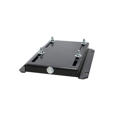
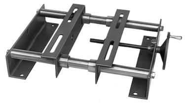
Are motor bases compatible with different types of motor mounts and couplings?
Motor bases are designed to be compatible with different types of motor mounts and couplings. Here’s a detailed explanation:
1. Motor Mounts: Motor bases typically provide standard mounting options that are compatible with various motor mount configurations. Common motor mount types include:
- Foot Mounts: Motor bases with foot mounts have slots or holes that align with the mounting feet on the motor. These bases allow for secure attachment and proper alignment of the motor.
- Flange Mounts: Some motors have flanges instead of feet for mounting. Motor bases designed for flange-mounted motors have matching flange patterns that ensure proper alignment and secure attachment.
- Face Mounts: In certain applications, motors are mounted directly to a surface using a face mount configuration. Motor bases compatible with face mounts provide the necessary mounting features, such as bolt patterns or mounting brackets, to facilitate this type of installation.
Motor bases are typically available in different configurations to accommodate these various motor mount types. This compatibility ensures that the motor base can securely and correctly mount different motor types, allowing for flexibility and ease of installation.
2. Motor Couplings: Motor bases are not directly involved in the coupling between the motor and driven equipment. The coupling is a separate component that connects the motor shaft to the driven shaft, such as a pump or gearbox. Motor bases do not have specific compatibility requirements with motor couplings.
However, it’s important to consider the space and clearance requirements for the coupling when selecting a motor base. Motor bases should provide adequate space for the coupling and allow for proper alignment between the motor and driven equipment.
Motor bases play a vital role in supporting and aligning the motor, irrespective of the type of motor mount or coupling used. They provide a secure and stable platform for mounting the motor, ensuring proper alignment, minimizing vibrations, and supporting the overall performance of the motor.
When selecting a motor base, it’s essential to consider the motor mount type specified by the motor manufacturer and ensure compatibility with the chosen base. Additionally, considering the space requirements for the motor coupling and its alignment with the driven equipment can help determine the appropriate motor base configuration.
In summary, motor bases are designed to be compatible with different types of motor mounts, including foot mounts, flange mounts, and face mounts. They provide the necessary features and configurations to securely and properly mount the motor. Motor bases are not directly involved in motor coupling, but they should accommodate the space and alignment requirements of the coupling. Considering motor mount compatibility and coupling clearance when selecting a motor base ensures a well-integrated and efficient motor installation.
How can users troubleshoot common issues related to motor base misalignment?
Troubleshooting common issues related to motor base misalignment can help ensure optimal performance and prevent potential problems. Here’s a detailed explanation:
1. Visual Inspection: Start by visually inspecting the motor base and its alignment with the driven equipment. Look for any obvious signs of misalignment, such as gaps, uneven contact, or skewed positioning. Pay attention to the alignment of coupling or drive belts, as they can indicate misalignment issues as well.
2. Measurements and Alignment Tools: Use precision measurement tools such as dial indicators, laser alignment devices, or straightedges to assess the alignment of the motor base. These tools can provide accurate measurements and help identify misalignment issues. Measure the alignment at multiple points along the motor base and compare the readings to the manufacturer’s recommended tolerances.
3. Check Mounting Bolts and Fasteners: Loose or improperly tightened mounting bolts and fasteners can contribute to motor base misalignment. Ensure that all bolts and fasteners are securely tightened according to the manufacturer’s specifications. If any bolts are found to be loose, tighten them appropriately. However, be cautious not to overtighten, as it can lead to deformation or misalignment of the motor base.
4. Assess Foundation or Mounting Surface: Examine the foundation or mounting surface on which the motor base is installed. Uneven or unstable surfaces can cause misalignment. Check for any irregularities, such as cracks, gaps, or soft spots, that may affect the alignment of the motor base. If necessary, repair or reinforce the foundation to ensure a stable and level mounting surface.
5. Alignment Adjustment: If misalignment is detected, make the necessary adjustments to bring the motor base into proper alignment. This may involve loosening the mounting bolts, adjusting shims or wedges, and repositioning the motor base. Follow the manufacturer’s guidelines or consult alignment experts for specific adjustment procedures based on the type of motor base and alignment method used.
6. Consider Thermal Growth: Account for thermal growth when aligning the motor base. Motors can experience thermal expansion or contraction during operation, which can affect alignment. Consult the manufacturer’s recommendations for thermal growth allowances and adjust the alignment accordingly.
7. Regular Maintenance: Implement a regular maintenance program that includes periodic inspections and realignment of the motor base. Over time, environmental factors, operational stresses, or equipment vibrations can cause misalignment. Regular maintenance helps identify and address misalignment issues before they escalate and lead to more severe problems.
8. Professional Assistance: If troubleshooting and adjustments do not resolve the misalignment issues, or if the alignment task requires specialized knowledge and equipment, seek assistance from alignment professionals or qualified technicians. They have the expertise and tools to accurately diagnose and correct complex misalignment problems.
It’s important to note that proper alignment of the motor base is essential for the smooth and efficient operation of the entire system. Misalignment can result in increased wear and tear, reduced energy efficiency, excessive vibration, premature component failure, and decreased overall performance. By promptly addressing misalignment issues, users can optimize the performance and lifespan of their motor base and associated equipment.
What materials are commonly used in the construction of durable motor bases?
Durable motor bases are constructed using various materials that provide strength, stability, and longevity. Here’s a detailed explanation:
Motor bases are designed to withstand the weight and operational forces of electric motors while maintaining stability and alignment. The choice of materials for motor base construction depends on factors such as the motor size, application requirements, and environmental conditions. Here are some commonly used materials:
1. Steel: Steel is one of the most commonly used materials for motor bases due to its exceptional strength and durability. Motor bases made of steel can withstand heavy loads and resist deformation. Steel motor bases are known for their rigidity, stability, and ability to dampen vibrations. They are suitable for a wide range of motor sizes and industrial applications.
2. Cast Iron: Cast iron is another popular material for motor bases, especially for larger motor sizes. Cast iron offers excellent stability and resistance to deformation under heavy loads. It has high compressive strength and can effectively absorb and dampen vibrations generated during motor operation. Cast iron motor bases are known for their long-lasting performance and suitability for demanding industrial environments.
3. Aluminum: Aluminum motor bases are commonly used for smaller or lighter motor applications. Aluminum is lightweight, corrosion-resistant, and offers good thermal conductivity. Motor bases made of aluminum are easy to handle and install. They are often preferred in applications where weight reduction is desired, such as in portable or mobile equipment.
4. Composite Materials: In some cases, motor bases may be constructed using composite materials such as fiberglass-reinforced plastic (FRP). Composite motor bases offer a combination of strength, lightweight construction, and corrosion resistance. They are particularly suitable for applications where weight reduction, electrical insulation, or resistance to chemicals and corrosive environments are important considerations.
5. Other Materials: Depending on specific requirements, motor bases can also be constructed using other materials such as stainless steel, galvanized steel, or specialized alloys. These materials may be chosen for their specific properties, such as resistance to corrosion, high-temperature applications, or compatibility with certain environmental conditions.
When selecting a motor base material, it’s essential to consider factors such as load capacity, environmental conditions (such as exposure to moisture, chemicals, or extreme temperatures), and the specific needs of the application.
In summary, durable motor bases are commonly constructed using materials such as steel, cast iron, aluminum, composite materials, and other specialized alloys. Each material offers specific advantages in terms of strength, stability, weight, corrosion resistance, and other properties, allowing motor bases to withstand the demands of industrial applications.


editor by CX 2024-04-04
China OEM High Power Helical Single Phase AC Gear Motor with High Torque Long Life dc motor
Product Description
TaiBang Motor Industry Group Co., Ltd.
The main products is induction motor, reversible motor, DC brush gear motor, DC brushless gear motor, CH/CV big gear motors, Planetary gear motor ,Worm gear motor etc, which used widely in various fields of manufacturing pipelining, transportation, food, medicine, printing, fabric, packing, office, apparatus, entertainment etc, and is the preferred and matched product for automatic machine.
Motor Model Instruction
5RK40GN-CM
| 5 | R | K | 40 | R | GN | C | M |
| Frame Size | Type | Motor series | Power | Speed Control Motor |
Shaft Type | Voltage | Accessory |
| 2:60mm
3:70mm 4:80mm 5:90mm 6:104mm |
I:Induction
R:Reversible T:Torque |
K series | 6W
15W 25W 40W 60W 90W 120W 140W 180W 200W |
A:Round Shaft
GN:Bevel Gear Shaft GU:Bevel Gear Shaft |
A:Single Phase 110V
C:Single Phase 220V S:3-Phase 220V S3:3-Phase 380V S4:3-Phase 440V |
T/P:Thermally Protected
F:Fan M:Electro-magnetic |
Gear Head Model Instruction
5GN-100K
| 5 | GN | 100 | K | |
| Frame Size | Shaft Type | Gear Reduction Ratio | Bearing Type | Other information |
| 2:60mm
3:70mm 4:80mm 5:90mm 6:104mm |
GN:Bevel Gear Shaft (60#,70#,80#,90# reduction gear head) GU:Bevel Gear Shaft GM:Intermediate Gear Head GS:Gearhead with ears |
1:100 | K:Standard Rolling Bearing
RT:Right Angle With Axile RC:Right Angle With Hollow Shaft |
Sch as shaft diameter,shaft length,etc. |
Specification of motor 40W 90mm Fixed speed AC gear motor
| Type | Gear Tooth Output Shaft | Power (W) |
Frequency (Hz) |
Voltage (V) |
Current (A) |
Start Torque (g.cm) |
Rated | Gearbox Type | ||
| Torque (g.cm) |
Speed (rpm) |
Bearing Gearbox | Middle Gearbox | |||||||
| Reversible Motor | 5RK40GN-C | 40 | 50 | 220 | 0.45 | 3000 | 3000 | 1300 | 5GN/GU-K | 5GN10X |
| 40 | 60 | 220 | 0.41 | 2500 | 2515 | 1550 | 5GN/GU-K | 5GN10X | ||
Gear Head Torque Table(Kg.cm) (kg.cm×9.8÷100)=N.m
| Output Speed :RPM | 500 | 300 | 200 | 150 | 120 | 100 | 75 | 60 | 50 | 30 | 20 | 15 | 10 | 7.5 | 6 | 5 | 3 | ||
| Speed Ratio | 50Hz | 3 | 5 | 7.5 | 10 | 12.5 | 15 | 20 | 25 | 30 | 50 | 75 | 100 | 150 | 200 | 250 | 300 | 500 | |
| 60Hz | 3.6 | 6 | 9 | 15 | 18 | 30 | 36 | 60 | 90 | 120 | 180 | 300 | 360 | 600 | |||||
| Allowed Torque |
40W | kg.cm | 6.7 | 11 | 16 | 21.3 | 28 | 33 | 42 | 54 | 65 | 108 | 150 | 150 | 150 | 150 | 150 | 150 | 150 |
| 60W | kg.cm | 10 | 16 | 24 | 32 | 40 | 48 | 64 | 77 | 93 | 150 | 150 | 150 | 150 | 150 | 150 | 150 | 150 | |
| 90W | kg.cm | 14 | 23 | 35 | 46 | 58 | 69 | 92 | 110 | 133 | 200 | 200 | 200 | 200 | 200 | 200 | 200 | 200 | |
| 120W | kg.cm | 19 | 30.7 | 46 | 61 | 77 | 92 | 123 | 147 | 177 | 200 | 200 | 200 | 200 | 200 | 200 | 200 | 200 | |
| Note: Speed figures are based on synchronous speed, The actual output speed, under rated torque conditions, is about 10-20% less than synchronous speed, a grey background indicates output shaft of geared motor rotates in the same direction as output shaft of motor. A white background indicates rotates rotation in the opposite direction. | |||||||||||||||||||
Drawing:5RK40GN-C/5GN3~20K(Short gearbox shell 43mm)
Drawing:5RK40GN-C/5GN25~180K(Short gearbox shell 61mm)
Above drawing is for standard screw hole.If need through hole, terminal box, or electronic magnet brake, need to tell the seller.
Connection Diagram:
| Application: | Industrial |
|---|---|
| Speed: | Constant Speed |
| Number of Stator: | Single-Phase |
| Function: | Driving, Control |
| Casing Protection: | Closed Type |
| Number of Poles: | 4 |
| Samples: |
US$ 50/Piece
1 Piece(Min.Order) | |
|---|
| Customization: |
Available
| Customized Request |
|---|

The Benefits of Using a Gear Motor
A gear motor works on the principle of conservation of angular momentum. As the smaller gear covers more RPM and the larger gear produces more torque, the ratio between the two is greater than one. Similarly, a multiple gear motor follows the principle of energy conservation, with the direction of rotation always opposite to the one that is adjacent to it. It’s easy to understand the concept behind gear motors and the various types available. Read on to learn about the different types of gears and their applications.
Electric motor
The choice of an electric motor for gear motor is largely dependent on the application. There are various motor and gearhead combinations available, and some are more efficient than others. However, it is critical to understand the application requirements and select a motor that meets these needs. In this article, we’ll examine some of the benefits of using a gear motor. The pros and cons of each type are briefly discussed. You can buy new gear motors at competitive prices, but they aren’t the most reliable or durable option for your application.
To determine which motor is best for your application, you’ll need to consider the load and speed requirements. A gear motor’s efficiency (e) can be calculated by taking the input and output values and calculating their relation. On the graph below, the input (T) and output (P) values are represented as dashed lines. The input (I) value is represented as the torque applied to the motor shaft. The output (P) is the amount of mechanical energy converted. A DC gear motor is 70% efficient at 3.75 lb-in / 2,100 rpm.
In addition to the worm gear motor, you can also choose a compact DC worm gear motor with a variable gear ratio from 7.5 to 80. It has a range of options and can be custom-made for your specific application. The 3-phase AC gear motor, on the other hand, works at a rated power of one hp and torque of 1.143.2 kg-m. The output voltage is typically 220V.
Another important factor is the output shaft orientation. There are two main orientations for gearmotors: in-line and offset. In-line output shafts are most ideal for applications with high torque and short reduction ratios. If you want to avoid backlash, choose a right angle output shaft. An offset shaft can cause the output shaft to become excessively hot. If the output shaft is angled at a certain angle, it may be too large or too small.
Gear reducer
A gear reducer is a special kind of speed reducing motor, usually used in large machinery, such as compressors. These reducers have no cooling fan and are not designed to handle heavy loads. Different purposes require different service factors. For instance, a machine that requires frequent fast accelerations and occasional load spikes needs a gear reducer with a high service factor. A gear reducer that’s designed for long production shifts should be larger than a machine that uses it for short periods of time.
A gear reducer can reduce the speed of a motor by a factor of two. The reduction ratio changes the rotation speed of the receiving member. This change in speed is often required to solve problems of inertia mismatch. The torque density of a gear reducer is measured in newton meters and will depend on the motor used. The first criterion is the configuration of the input and output shafts. A gear ratio of 2:1, for example, means that the output speed has been cut in half.
Bevel gear reducers are a good option if the input and output shafts are perpendicular. This type is very robust and is perfect for situations where the angle between two axes is small. However, bevel gear reducers are expensive and require constant maintenance. They are usually used in heavy-duty conveyors and farm equipment. The correct choice of gear reducer for gear motor is crucial for the efficiency and reliability of the mechanism. To get the best gear reducer for your application, talk to a qualified manufacturer today.
Choosing a gear reducer for a gear motor can be tricky. The wrong one can ruin an entire machine, so it’s important to know the specifics. You must know the torque and speed requirements and choose a motor with the appropriate ratio. A gear reducer should also be compatible with the motor it’s intended for. In some cases, a smaller motor with a gear reducer will work better than a larger one.
Motor shaft
Proper alignment of the motor shaft can greatly improve the performance and life span of rotating devices. The proper alignment of motors and driven instruments enhances the transfer of energy from the motor to the instrument. Incorrect alignment leads to additional noise and vibration. It may also lead to premature failure of couplings and bearings. Misalignment also results in increased shaft and coupling temperatures. Hence, proper alignment is critical to improve the efficiency of the driven instrument.
When choosing the correct type of gear train for your motor, you need to consider its energy efficiency and the torque it can handle. A helical geared motor is more efficient for high output torque applications. Depending on the required speed and torque, you can choose between an in-line and a parallel helical geared motor. Both types of gears have their advantages and disadvantages. Spur gears are widespread. They are toothed and run parallel to the motor shaft.
A planetary gear motor can also have a linear output shaft. A stepping motor should not operate at too high current to prevent demagnetization, which will lead to step loss or torque drop. Ensure that the motor and gearbox output shafts are protected from external impacts. If the motor and gearbox are not protected against bumps, they may cause thread defects. Make sure that the motor shafts and rotors are protected from external impacts.
When choosing a metal for your gear motor’s motor shaft, you should consider the cost of hot-rolled bar stock. Its outer layers are more difficult to machine. This type of material contains residual stresses and other problems that make it difficult to machine. For these applications, you should choose a high-strength steel with hard outer layers. This type of steel is cheaper, but it also has size considerations. It’s best to test each material first to determine which one suits your needs.
In addition to reducing the speed of your device, a geared motor also minimizes the torque generated by your machine. It can be used with both AC and DC power. A high-quality gear motor is vital for stirring mechanisms and conveyor belts. However, you should choose a geared motor that uses high-grade gears and provides maximum efficiency. There are many types of planetary gear motors and gears on the market, and it’s important to choose the right one.
First stage gears
The first stage gears of a gear motor are the most important components of the entire device. The motor’s power transmission is 90% efficient, but there are many factors that can affect its performance. The gear ratios used should be high enough to handle the load, but not too high that they are limiting the motor’s speed. A gear motor should also have a healthy safety factor, and the lubricant must be sufficient to overcome any of these factors.
The transmission torque of the gear changes with its speed. The transmission torque at the input side of the gear decreases, transferring a small torque to the output side. The number of teeth and the pitch circle diameters can be used to calculate the torque. The first stage gears of gear motors can be categorized as spur gears, helical gears, or worm gears. These three types of gears have different torque capacities.
The first stage helical gear is the most important part of a gear motor. Its function is to transfer rotation from one gear to the other. Its output is the gearhead. The second stage gears are connected by a carrier. They work in tandem with the first stage gear to provide the output of the gearhead. Moreover, the first stage carrier rotates in the same direction as the input pinion.
Another important component is the output torque of the gearmotor. When choosing a gearmotor, consider the starting torque, running torque, output speed, overhung and shock loads, duty cycles, and more. It is crucial to choose a gearmotor with the right ratio for the application. By choosing the proper gearmotor, you will get maximum performance with minimal operating costs and increase plant productivity. For more information on first stage gears, check out our blog.
The first stage of a gear motor is composed of a set of fixed and rotating sprockets. The first stage of these gears acts as a drive gear. Its rotational mass is a limiting factor for torque. The second stage consists of a rotating shaft. This shaft rotates in the direction of the torque axis. It is also the limiting force for the motor’s torque.
editor by CX 2023-11-13
China Solar Photovoltaic PV System Tracking Nmrv Worm Reducer Electric Engine Slew Drive Hydraulic Single Dual Axis Linear Actuator Planetary DC Tracker Gear Motor with Great quality
Product Description
Solar Photovoltaic PV System Tracking NMRV Worm Reducer Electric Engine Slew Drive Hydraulic Single Dual Axis Linear Actuator Planetary DC Tracker Gear Motor
Product Description
Solar tracker motor is also named solar tracking system controlling motor, it is used for solar power generation equipment. The motor has a very low speed, generally, 1~3 rpm which accords with the feature of a DC planetary gear motor. Because the reduction ratio of the planetary gearbox can be very large to achieve very low speed.
The following DC planetary gear motors, stepping planetary gear motors can resist and work well in bad weather conditions with their safe and reliable use, and meet the demands of small and medium automatic tracking systems.
Detailed Photos
Typical applications
Product Parameters
|
No |
Model |
A52R50D24 |
|
1 |
Drive series |
4 |
|
2 |
Gearbox Ratio |
860.6:1 |
|
3 |
Rated output torque |
400 Nm |
|
4 |
Max torque |
320 Nm |
|
5 |
Rated output speed |
1 rpm |
|
6 |
Rated current (A) |
5 |
|
7 |
Rated voltage(v) |
24 |
|
8 |
Noise (dB) |
≤60 |
|
9 |
Working temperature(ºC) |
-40~80 |
|
10 |
IP Grade |
IP65 |
Our Advantages
Company Profile
FAQ
Q: Can you make the gear motor with customization?
A: Yes, we can customize per your request, like power, voltage, speed, shaft size, wires, connectors, IP grade, etc.
Q: Do you provide samples?
A: Yes. The sample is available for testing.
Q: What is your MOQ?
A: It is 10pcs for the beginning of our business.
Q: What’s your lead time?
A: Standard products need 5-30days, a bit longer for customized products.
Q: Do you provide technical support?
A: Yes. Our company have design and development team, we can provide technical support if you
need.
Q: How to ship to us?
A: It is available by air, or by sea, or by train.
Q: How to pay the money?
A: T/T and L/C are preferred, with a different currency, including USD, EUR, RMB, etc.
Q: How can I know the product is suitable for me?
A: >1ST confirm drawing and specification >2nd test sample >3rd start mass production.
Q: Can I come to your company to visit?
A: Yes, you are welcome to visit us at any time.
Q: How shall we contact you?
A: You can send an inquiry directly, and we will respond within 24 hours.
|
US $20-50 / Piece | |
1 Piece (Min. Order) |
###
|
Shipping Cost:
Estimated freight per unit. |
To be negotiated |
|---|
###
| Application: | Solar Photovoltaic |
|---|---|
| Operating Speed: | Constant Speed |
| Excitation Mode: | Excited |
###
| Samples: |
US$ 50/Piece
1 Piece(Min.Order) 1 pc per carton
|
|---|
###
| Customization: |
Available
|
|---|
###
|
No
|
Model
|
A52R50D24
|
|
1
|
Drive series
|
4
|
|
2
|
Gearbox Ratio
|
860.6:1
|
|
3
|
Rated output torque
|
400 Nm
|
|
4
|
Max torque
|
320 Nm
|
|
5
|
Rated output speed
|
1 rpm
|
|
6
|
Rated current (A)
|
5
|
|
7
|
Rated voltage(v)
|
24
|
|
8
|
Noise (dB)
|
≤60
|
|
9
|
Working temperature(ºC)
|
-40~80
|
|
10
|
IP Grade
|
IP65
|
|
US $20-50 / Piece | |
1 Piece (Min. Order) |
###
|
Shipping Cost:
Estimated freight per unit. |
To be negotiated |
|---|
###
| Application: | Solar Photovoltaic |
|---|---|
| Operating Speed: | Constant Speed |
| Excitation Mode: | Excited |
###
| Samples: |
US$ 50/Piece
1 Piece(Min.Order) 1 pc per carton
|
|---|
###
| Customization: |
Available
|
|---|
###
|
No
|
Model
|
A52R50D24
|
|
1
|
Drive series
|
4
|
|
2
|
Gearbox Ratio
|
860.6:1
|
|
3
|
Rated output torque
|
400 Nm
|
|
4
|
Max torque
|
320 Nm
|
|
5
|
Rated output speed
|
1 rpm
|
|
6
|
Rated current (A)
|
5
|
|
7
|
Rated voltage(v)
|
24
|
|
8
|
Noise (dB)
|
≤60
|
|
9
|
Working temperature(ºC)
|
-40~80
|
|
10
|
IP Grade
|
IP65
|
How to Assemble a Planetary Motor
A Planetary Motor uses multiple planetary surfaces to produce torque and rotational speed. The planetary system allows for a wide range of gear reductions. Planetary systems are particularly effective in applications where higher torques and torque density are needed. As such, they are a popular choice for electric vehicles and other applications where high-speed mobility is required. Nevertheless, there are many benefits associated with using a planetary motor. Read on to learn more about these motors.
VPLite
If you’re looking to replace the original VP, the VPLite has a similar output shaft as the original. This means that you can mix and match your original gear sets, including the input and output shafts. You can even mix metal inputs with plastic outputs. Moreover, if you decide to replace the gearbox, you can easily disassemble the entire unit and replace it with a new one without losing any output torque.
Compared to a planetary motor, a spur gear motor uses fewer gears and is therefore cheaper to produce. However, the latter isn’t suitable for high-torque applications. The torque produced by a planetary gearmotor is evenly distributed, which makes it ideal for applications that require higher torque. However, you may have to compromise on the torque output if you’re looking for a lightweight option.
The VersaPlanetary Lite gearbox replaces the aluminum ring gear with a 30% glass-filled nylon gear. This gearbox is available in two sizes, which means you can mix and match parts to get a better gear ratio. The VPLite gearbox also has a female 5mm hex output shaft. You can mix and match different gearboxes and planetary gearboxes for maximum efficiency.
VersaPlanetary
The VersaPlanetary is a highly versatile planetary motor that can be mounted in a variety of ways. Its unique design includes a removable shaft coupler system that makes it simple to swap out the motor with another. This planetary motor mounts in any position where a CIM motor mounts. Here’s how to assemble the motor. First, remove the hex output shaft from the VersaPlanetary output stage. Its single ring clip holds it in place. You can use a drill press to drill a hole into the output shaft.
After mounting the gearbox, you can then mount the motor. The mounting hardware included with the VersaPlanetary Planetary Motor comes with four 10-32 threaded holes on a two-inch bolt circle. You can use these holes to mount your VersaPlanetary on a CIM motor or a CIM-compatible motor. Once assembled, the VersaPlanetary gearbox has 72 different gear ratios.
The VersaPlanetary gearbox is interchangeable with regular planetary gearboxes. However, it does require additional parts. You can purchase a gearbox without the motor but you’ll need a pinion. The pinion attaches to the shaft of the motor. The gearbox is very sturdy and durable, so you won’t have to worry about it breaking or wearing out.
Self-centering planetary gears
A planetary motor is a simple mechanical device that rotates around a axis, with the planets moving around the shaft in a radial direction. The planets are positioned so that they mesh with both the sun gear and the output gears. The carrier 48 is flexibly connected to the drive shaft and can move depending on the forces exerted by the planet gears. In this way, the planets can always be in the optimal mesh with the output gears and sun gear.
The first step in developing a planetary gear motor is to identify the number of teeth in each planet. The number of teeth should be an integer. The tooth diameters of the planets should mesh with each other and the ring. Typically, the teeth of one planet must mesh with each other, but the spacing between them must be equal or greater than the other. This can be achieved by considering the tooth count of each planet, as well as the spacing between planets.
A second step is to align the planet gears with the output gears. In a planetary motor, self-centering planetary gears must be aligned with both input and output gears to provide maximum torque. For this to be possible, the planet gears must be connected with the output shaft and the input shaft. Similarly, the output shaft should also be able to align with the input gear.
Encoders
A planetary geared motor is a DC motor with a planetary gearbox. The motor can be used to drive heavy loads and has a ratio of 104:1. The shaft speed is 116rpm when it is unloaded. A planetary gearbox has a low backlash and is often used in applications that need high torque. Planetary Motor encoders can help you keep track of your robot’s position or speed.
They are also able to control motor position and speed with precision. Most of them feature high resolution. A 0.18-degree resolution encoder will give you a minimum of 2000 transitions per rotation between outputs A and B. The encoder is built to industrial standards and has a sturdy gearbox to avoid damage. The encoder’s robust design means it will not stall when the motor reaches its maximum speed.
There are many advantages to a planetary motor encoder. A high-quality one will not lose its position or speed even if it’s subject to shocks. A good quality planetary motor will also last a long time. Planetary motors are great for resale or for your own project. If you’re considering buying a planetary motor, consider this information. It’ll help you decide if a particular model is right for your needs.
Cost
There are several advantages of planetary motors. One of the biggest is their cost, but they can also be used in many different applications. They can be combined with a variety of gearboxes, and are ideal for various types of robots, laboratory automation, and production applications. Planetary gearboxes are available in many different materials, and plastic planetary gearboxes are an economical alternative. Plastic gearboxes reduce noise at higher speeds, and steel input stage gears are available for high torques. A modified lubrication system can help with difficult operating conditions.
In addition to being more durable, planetary motors are much more efficient. They use fewer gears, which lowers the overall cost of production. Depending on the application, a planetary motor can be used to move a heavy object, but is generally less expensive than its counterpart. It is a better choice for situations where the load is relatively low and the motor is not used frequently. If you need a very high torque output, a planetary motor may be the better option.
Planetary gear units are a good choice for applications requiring high precision, high dynamics, and high torque density. They can be designed and built using TwinCAT and TC Motion Designer, and are delivered as complete motor and gear unit assemblies. In a few simple steps, you can calculate the torque required and compare the costs of different planetary gear units. You can then choose the best model for your application. And because planetary gear units are so efficient, they are a great option for high-end industrial applications.
Applications
There are several different applications of the planetary motor. One such application is in motion control. Planetary gearboxes have many benefits, including high torque, low backlash, and torsional stiffness. They also have an extremely compact design, and can be used for a variety of applications, from rack and pinion drives to delta robotics. In many cases, they are less expensive to manufacture and use than other types of motors.
Another application for planetary gear units is in rotary tables. These machines require high precision and low backlash for their precise positioning. Planetary gears are also necessary for noise reduction, which is a common feature in rotary tables. High precision planetary gears can make the height adjustment of OP tables a breeze. And because they are extremely durable and require low noise, they are a great choice for this application. In this case, the planetary gear is matched with an AM8000 series servomotor, which gives a wide range of choices.
The planetary gear transmission is also widely used in helicopters, automobiles, and marine applications. It is more advanced than a countershaft drive, and is capable of higher torque to weight ratios. Other advantages include its compact design and reduced noise. A key concern in the development of this type of transmission is to minimize vibration. If the output of a planetary gear transmission system is loud, the vibration caused by this type of drive system may be too loud for comfort.
editor by czh 2022-12-01
China Factory wholesale YL series 1HP 0.75KW motor single phase 1500rpm 3000rpm 220V 2HP 3HP 5HP 7.5HP 10HP electric motor with Best Sales
Model Number: YL71
Type: Induction Motor
Frequency: 50/60HZ
Phase: Single-phase
Protect Feature: Totally Enclosed
AC Voltage: 380V/220V
Efficiency: IE 2
Application: General Machinery
Protection class: IP44/IP54/IP55
Housing: Aluminium/Cast Iron
Winding: 100% Copper Wire
Color: Customer Request
Function: Drving
Warranty: 1 Year
Structure: IMB3/B5/B35/V1
Noise: less than 65dBA
Cooling method: ICO141
Packaging Details: 1.cartons inside,wooden cases outside 2.special customer require
Port: NIngbo or ZheJiang
Rated Speed 910~2840rpm Ac single Phase Electric Motor
Motor photo:
Technical data:
Motor parameters
| Voltage: | 220/380V |
| Frequency: | 50Hz/60Hz |
| Power: | 0.12 kW~22 kW (0.16HP~30HP) |
| Poles: | 2P, 4P, 6P |
| Output Speed: | 3000RPM, 1500RPM, 1000RPM |
| Frame Sizes: | H63~H180 |
| Shaft Diameter: | Φ11~Φ48 |
| Ingress Protection: | IP54, IP55, IP56 |
| Insulation Level: | F |
| Duty: | Continuous duty (S1) |
| Cooling: | IC411 |
Motor drawing:
Motor parts:
We use 100% copper wires,biggest permeability, with long service life
Company InformationHangZhou Hengbai Manufacturer was founded in 1998. As a national key manufacturer, our factory covers an area more than 90,000 square meters, workers about 100, include 10 technical person, as well as 32 sets production equipments. Design and production capacity can reach 1 million KW. With an annual output of motors more than 2 thousand units. Almost 30 years experiences, our manufacturer has accumulated a large number of experienced and skilled industrial workers and engineering and technical personnel. Mainly produce low voltage Y, Y2, YE2, YE3, JR, YZR series and high voltage Y, YR, YKK, YXKK, YKS series and DC series motors more than 20 kinds 500 models 3 phase asynchronous electric motors, DC motors, synchronous motors and VFD electric motors, with high efficiency and energy saving, economization on power and material consumption. Besides, we also do OEM to meet their diversified and personalized needs.
Packaging & Shipping
Our Services Prompt Quotation ++ Competitive Price ++ Guaranteed Quality ++ Timely Delivery ++ 100% Tested ++ Sincere and Professional Service ++ Outstanding Finishing Surface ++ Strictly and Perfect Management is guaranteed for Production ++ Have Rich Experience and Strong ability to Develop New Products ++ Have Ability to Design the Products Based on Your Original Samples.
FAQ
Process Of An Order:
1. Please check product detailed information above.
A. Model/Size B. Transmission Ratio C. Shaft Direction D. Order Quantity.
2. Our Export Service Team will contact you with a quotation file within 3 hours after our team get your enquiry.
3. When you place an order, our team will confirm with you about color, package,method of payment and delivery,
then a sales contract will be sent to you to confirm.
4. Packing: Carton and Wooden Case.
5. How to delivery:
By sea – Buyer appoint forwarder, or our sales team find suitable forwarder for buyers.
By air – Buyer offer collect express account, or our sales team find suitable express for buyers. (Mostly for sample)
Others – We arrange to delivery goods to some place in China appoint by buyers.
Welcome To Visit Our Factory – Located in the tourism city – HangZhou -West Lake.
Dynamic Modeling of a Planetary Motor
A planetary gear motor consists of a series of gears rotating in perfect synchrony, allowing them to deliver torque in a higher output capacity than a spur gear motor. Unlike the planetary motor, spur gear motors are simpler to build and cost less, but they are better for applications requiring lower torque output. That is because each gear carries the entire load. The following are some key differences between the two types of gearmotors.
planetary gear system
A planetary gear transmission is a type of gear mechanism that transfers torque from one source to another, usually a rotary motion. Moreover, this type of gear transmission requires dynamic modeling to investigate its durability and reliability. Previous studies included both uncoupled and coupled meshing models for the analysis of planetary gear transmission. The combined model considers both the shaft structural stiffness and the bearing support stiffness. In some applications, the flexible planetary gear may affect the dynamic response of the system.
In a planetary gear device, the axial end surface of the cylindrical portion is rotatable relative to the separating plate. This mechanism retains lubricant. It is also capable of preventing foreign particles from entering the planetary gear system. A planetary gear device is a great choice if your planetary motor’s speed is high. A high-quality planetary gear system can provide a superior performance than conventional systems.
A planetary gear system is a complex mechanism, involving three moving links that are connected to each other through joints. The sun gear acts as an input and the planet gears act as outputs. They rotate about their axes at a ratio determined by the number of teeth on each gear. The sun gear has 24 teeth, while the planet gears have three-quarters that ratio. This ratio makes a planetary motor extremely efficient.
planetary gear train
To predict the free vibration response of a planetary motor gear train, it is essential to develop a mathematical model for the system. Previously, static and dynamic models were used to study the behavior of planetary motor gear trains. In this study, a dynamic model was developed to investigate the effects of key design parameters on the vibratory response. Key parameters for planetary gear transmissions include the structure stiffness and mesh stiffness, and the mass and location of the shaft and bearing supports.
The design of the planetary motor gear train consists of several stages that can run with variable input speeds. The design of the gear train enables the transmission of high torques by dividing the load across multiple planetary gears. In addition, the planetary gear train has multiple teeth which mesh simultaneously in operation. This design also allows for higher efficiency and transmittable torque. Here are some other advantages of planetary motor gear trains. All these advantages make planetary motor gear trains one of the most popular types of planetary motors.
The compact footprint of planetary gears allows for excellent heat dissipation. High speeds and sustained performances will require lubrication. This lubricant can also reduce noise and vibration. But if these characteristics are not desirable for your application, you can choose a different gear type. Alternatively, if you want to maintain high performance, a planetary motor gear train will be the best choice. So, what are the advantages of planetary motor gears?
planetary gear train with fixed carrier train ratio
The planetary gear train is a common type of transmission in various machines. Its main advantages are high efficiency, compactness, large transmission ratio, and power-to-weight ratio. This type of gear train is a combination of spur gears, single-helical gears, and herringbone gears. Herringbone planetary gears have lower axial force and high load carrying capacity. Herringbone planetary gears are commonly used in heavy machinery and transmissions of large vehicles.
To use a planetary gear train with a fixed carrier train ratio, the first and second planets must be in a carrier position. The first planet is rotated so that its teeth mesh with the sun’s. The second planet, however, cannot rotate. It must be in a carrier position so that it can mesh with the sun. This requires a high degree of precision, so the planetary gear train is usually made of multiple sets. A little analysis will simplify this design.
The planetary gear train is made up of three components. The outer ring gear is supported by a ring gear. Each gear is positioned at a specific angle relative to one another. This allows the gears to rotate at a fixed rate while transferring the motion. This design is also popular in bicycles and other small vehicles. If the planetary gear train has several stages, multiple ring gears may be shared. A stationary ring gear is also used in pencil sharpener mechanisms. Planet gears are extended into cylindrical cutters. The ring gear is stationary and the planet gears rotate around a sun axis. In the case of this design, the outer ring gear will have a -3/2 planet gear ratio.
planetary gear train with zero helix angle
The torque distribution in a planetary gear is skewed, and this will drastically reduce the load carrying capacity of a needle bearing, and therefore the life of the bearing. To better understand how this can affect a gear train, we will examine two studies conducted on the load distribution of a planetary gear with a zero helix angle. The first study was done with a highly specialized program from the bearing manufacturer INA/FAG. The red line represents the load distribution along a needle roller in a zero helix gear, while the green line corresponds to the same distribution of loads in a 15 degree helix angle gear.
Another method for determining a gear’s helix angle is to consider the ratio of the sun and planet gears. While the sun gear is normally on the input side, the planet gears are on the output side. The sun gear is stationary. The two gears are in engagement with a ring gear that rotates 45 degrees clockwise. Both gears are attached to pins that support the planet gears. In the figure below, you can see the tangential and axial gear mesh forces on a planetary gear train.
Another method used for calculating power loss in a planetary gear train is the use of an auto transmission. This type of gear provides balanced performance in both power efficiency and load capacity. Despite the complexities, this method provides a more accurate analysis of how the helix angle affects power loss in a planetary gear train. If you’re interested in reducing the power loss of a planetary gear train, read on!
planetary gear train with spur gears
A planetary gearset is a type of mechanical drive system that uses spur gears that move in opposite directions within a plane. Spur gears are one of the more basic types of gears, as they don’t require any specialty cuts or angles to work. Instead, spur gears use a complex tooth shape to determine where the teeth will make contact. This in turn, will determine the amount of power, torque, and speed they can produce.
A two-stage planetary gear train with spur gears is also possible to run at variable input speeds. For such a setup, a mathematical model of the gear train is developed. Simulation of the dynamic behaviour highlights the non-stationary effects, and the results are in good agreement with the experimental data. As the ratio of spur gears to spur gears is not constant, it is called a dedendum.
A planetary gear train with spur gears is a type of epicyclic gear train. In this case, spur gears run between gears that contain both internal and external teeth. The circumferential motion of the spur gears is analogous to the rotation of planets in the solar system. There are four main components of a planetary gear train. The planet gear is positioned inside the sun gear and rotates to transfer motion to the sun gear. The planet gears are mounted on a joint carrier that is connected to the output shaft.
planetary gear train with helical gears
A planetary gear train with helical teeth is an extremely powerful transmission system that can provide high levels of power density. Helical gears are used to increase efficiency by providing a more efficient alternative to conventional worm gears. This type of transmission has the potential to improve the overall performance of a system, and its benefits extend far beyond the power density. But what makes this transmission system so appealing? What are the key factors to consider when designing this type of transmission system?
The most basic planetary train consists of the sun gear, planet gear, and ring gear elements. The number of planets varies, but the basic structure of planetary gears is similar. A simple planetary geartrain has the sun gear driving a carrier assembly. The number of planets can be as low as two or as high as six. A planetary gear train has a low mass inertia and is compact and reliable.
The mesh phase properties of a planetary gear train are particularly important in designing the profiles. Various parameters such as mesh phase difference and tooth profile modifications must be studied in depth in order to fully understand the dynamic characteristics of a PGT. These factors, together with others, determine the helical gears’ performance. It is therefore essential to understand the mesh phase of a planetary gear train to design it effectively.
editor by czh
China OEM YL 220v415v 1.5KW 20HP Ac Electric Motors Single phase Three phase Two value Stepper Motor near me supplier
Warranty: 1 year
Model Number: YE2 YC YL YS
Type: Induction Motor, Ac Electric Motors Single phase Three phase Two value Stepper Motor
Frequency: 50HZ/60HZ
Phase: Three-phase
Protect Feature: Drip-proof
AC Voltage: 208-230 / 240 V
Efficiency: Ie 3, 92%~96%
Power: 0.18-315kw
Pole: 2/4/6/8 pole
Application: gear box, transmission,bander rotary cultivator powered harrow,crusher
Material: copper coil Cast Iron Casing
Working temperature: -40~45℃
Process: Carburizing, Nitriding , Grinding
Mounting Position: Horizontal,Vertical,Flange
Color: Blue,Green,Gray,Red
Packaging Details: sea worthy wooden case for YL 220v/415v 1.5KW 20HP Ac Electric Motors Single phase Three phase Two value Stepper Motor
Product Overview PROFESSIONAL MANUFACTURE—— SINCE 1995Three phase single engine YE2 YS YL electric motorChinese electric motor speed reducer is widely used in mining machinery, chemical industry,steel metallurgy, lightindustry,environmental protection, paper making, printing, lifting transport, food industry and so on. Main Series Product: R series helical gear motor reducer, K series spiral bevel gear reducer motor, NGW, P series Planetary Gear reducer, H B series gearbox, Z (ZDY, ZLY, ZSY, and ZFY) serial hard tooth surface cylindrical gear reducer box, D (DBY and DCY) serial hard tooth surface cone gear reducer, cycloid reducer, ZLYJ Extruder Gearbox etc. Meanwhile, map sample processing business can be undertaken. FEATURES AT A GLANCE YE2 YS YL electric motor● It realized serialization and modularization with compact structure and wide range of transmission ratio. ● The transmission efficiency reach up to 96%.● Adopt Cooper coil ● High efficiency, superior performance with less energy consumption High precision gear, steady transmission, low noise, large load capacity, long service life.● Support various of installation method. Spiral Bevel Gear Motor Worm Gear Motor Vertical type for Agitator PRODUCT SPECIFICATIONS PhaseSingle/Three PhasePole2468Power(kw)0.18-375KWFrequency(hz)50/6050/60Speed(rpm)3000155710571 YE2 YS YL electric motorGear Reducer is a mechanical transmission in many fields of the national economy. The product categories covered by the industry include all kinds of gear reducer, planetary gear reducer and worm reducer, as well as various special transmission devices such as speed increasing device, speed control Devices, including various types of flexible transmission devices, such as compound transmission. Products and services in the field of metallurgy, nonferrous metals, coal, building materials, ships, water conservancy, electricity, construction machinery and petrochemical industries.In all fields of national economy and national defense industry, gearbox products have a wide range of applications. Food light industry, electric machinery, construction machinery, metallurgy machinery, cement machinery, environmental protection machinery,electronic appliances, road construction machinery, water conservancy machinery, chemical machinery, mining machinery, conveyor machinery, building materials machinery, rubber machinery, petroleum machinery and other industries have strong demand of Reducer products.YL 220v/415v 1.5KW 20HP Ac Electric Motors Single phase Three phase Two value Stepper Motor PRODUCT CONFIGURATION Working principle of gear reducerWhen the output speed of the motor of the gear reducer is input from the driving shaft, the small gear of the reducer will move. The large gear is linked with the small gear, so the movement of the small gear will drive the movement of the large gear. The number of teeth is more than the number of teeth on the pinion, so the speed of the big gear will be slower than that of the pinion, and then output through the output shaft of the big gear, thus playing the role of output deceleration.Gear reducer application rangeThe gear used in the gear reducer is carbon-quenched and high-strength low-carbon alloy steel, which has a high design and manufacturing process, and also has the characteristics of good foundation and high precision of the tooth surface.Gear reducers are generally used in low-speed and high-torque transmission equipment,it have extremely common applications in the transmission and drive fields of textile, printing and dyeing, light industry, food, metallurgy, mining, petroleum,chemical, construction, transportation, machinery and other industries.The role of gear reducer1. Slow down. Deceleration In industrial production, it is often necessary to use different frequency rates to produce operations. The gear reducer changes the frequency conversion deceleration of the equipment during operation through a certain function.2. Change the torque. The gear reducer achieves the purpose of changing the speed of the equipment by changing the torque. Different equipment has different maximum torque values and cannot exceed that value.3. Reduce inertia. The gear reducer will reduce the inertia of the target machine while working. 20CrMnTi Hard Tooth Gear Copper Coil High Quality Electric Motor Famous Brand Bearings Company Profile Established in 1995 , HangZhou Boji Machinery is a professional manufacturer and exporter that is concerned with the design, development and production of Gearbox Speed Reducer. We are located in HangZhou of ZheJiang Province, with convenient transportation access. With our own brand “TianQi”, all of our products comply with international quality standards and are greatly appreciated in a variety of different markets throughout the world.Our company possesses complete machining center, lathe, gear shaping machine, gear milling machine, gear grinding machine and assembling lines. Our well-equipped facilities and excellent quality control throughout all stages of production enables us to guarantee total customer satisfaction.Besides, In 2005,we attained ISO9001 certification. As a result of our high quality products and outstanding customer service, we have gained a global sales network CZPT South America, Saudi Arabia, Vietnam, Pakistan, Philippines, South Africa and other countries and regions. Successful Project SIMILAR PRODUCTS FAQ 1. Who are we?We are the Factory, with over 25 years of production experience, based in ZheJiang , China, start from 1995,sell to DomesticMarket(50.00%),Mid East(10.00%),Southeast Asia(10.00%),Western Europe(5.00%),South America(5.00%),Eastern Europe(5.00%),EasternAsia(5.00%),North America(3.00%),Africa(2.00%),Southern Europe(2.00%),South Asia(2.00%),Central America(1.00%). 2. Can you customize according to our requirements?Yes, we can design nonstandard products according to customer’s drawing and sample.3. What can you buy from us?speed reducer,gearbox,gear motor,pump,crusher4. Why should you buy from us not from other suppliers?Founded in 1995, with over 20 years of production experience and credibility. With professional engineer team, advanced technologyproduction and skilled workers.Specialized in the production of reducer. Map sample processing business can be undertaken.5. What services can we provide?Accepted Delivery Terms: FOB,CFR,CIF,EXW,DDP,DDU,Express Delivery;Accepted Payment Currency:USD,EUR,JPY,CAD,AUD,HKD,GBP,CNY,CHF;Accepted Payment Type: T/T,L/C,Credit Card,PayPal,Western Union,Cash;Language Spoken:English,Chinese,Spanish,Japanese,Portuguese,German,Arabic,French,Russian,Korean,Hindi,Italian
The Benefits of Using a Gear Motor
A gear motor works on the principle of conservation of angular momentum. As the smaller gear covers more RPM and the larger gear produces more torque, the ratio between the two is greater than one. Similarly, a multiple gear motor follows the principle of energy conservation, with the direction of rotation always opposite to the one that is adjacent to it. It’s easy to understand the concept behind gear motors and the various types available. Read on to learn about the different types of gears and their applications.
Electric motor
The choice of an electric motor for gear motor is largely dependent on the application. There are various motor and gearhead combinations available, and some are more efficient than others. However, it is critical to understand the application requirements and select a motor that meets these needs. In this article, we’ll examine some of the benefits of using a gear motor. The pros and cons of each type are briefly discussed. You can buy new gear motors at competitive prices, but they aren’t the most reliable or durable option for your application.
To determine which motor is best for your application, you’ll need to consider the load and speed requirements. A gear motor’s efficiency (e) can be calculated by taking the input and output values and calculating their relation. On the graph below, the input (T) and output (P) values are represented as dashed lines. The input (I) value is represented as the torque applied to the motor shaft. The output (P) is the amount of mechanical energy converted. A DC gear motor is 70% efficient at 3.75 lb-in / 2,100 rpm.
In addition to the worm gear motor, you can also choose a compact DC worm gear motor with a variable gear ratio from 7.5 to 80. It has a range of options and can be custom-made for your specific application. The 3-phase AC gear motor, on the other hand, works at a rated power of one hp and torque of 1.143.2 kg-m. The output voltage is typically 220V.
Another important factor is the output shaft orientation. There are two main orientations for gearmotors: in-line and offset. In-line output shafts are most ideal for applications with high torque and short reduction ratios. If you want to avoid backlash, choose a right angle output shaft. An offset shaft can cause the output shaft to become excessively hot. If the output shaft is angled at a certain angle, it may be too large or too small.
Gear reducer
A gear reducer is a special kind of speed reducing motor, usually used in large machinery, such as compressors. These reducers have no cooling fan and are not designed to handle heavy loads. Different purposes require different service factors. For instance, a machine that requires frequent fast accelerations and occasional load spikes needs a gear reducer with a high service factor. A gear reducer that’s designed for long production shifts should be larger than a machine that uses it for short periods of time.
A gear reducer can reduce the speed of a motor by a factor of two. The reduction ratio changes the rotation speed of the receiving member. This change in speed is often required to solve problems of inertia mismatch. The torque density of a gear reducer is measured in newton meters and will depend on the motor used. The first criterion is the configuration of the input and output shafts. A gear ratio of 2:1, for example, means that the output speed has been cut in half.
Bevel gear reducers are a good option if the input and output shafts are perpendicular. This type is very robust and is perfect for situations where the angle between two axes is small. However, bevel gear reducers are expensive and require constant maintenance. They are usually used in heavy-duty conveyors and farm equipment. The correct choice of gear reducer for gear motor is crucial for the efficiency and reliability of the mechanism. To get the best gear reducer for your application, talk to a qualified manufacturer today.
Choosing a gear reducer for a gear motor can be tricky. The wrong one can ruin an entire machine, so it’s important to know the specifics. You must know the torque and speed requirements and choose a motor with the appropriate ratio. A gear reducer should also be compatible with the motor it’s intended for. In some cases, a smaller motor with a gear reducer will work better than a larger one.
Motor shaft
Proper alignment of the motor shaft can greatly improve the performance and life span of rotating devices. The proper alignment of motors and driven instruments enhances the transfer of energy from the motor to the instrument. Incorrect alignment leads to additional noise and vibration. It may also lead to premature failure of couplings and bearings. Misalignment also results in increased shaft and coupling temperatures. Hence, proper alignment is critical to improve the efficiency of the driven instrument.
When choosing the correct type of gear train for your motor, you need to consider its energy efficiency and the torque it can handle. A helical geared motor is more efficient for high output torque applications. Depending on the required speed and torque, you can choose between an in-line and a parallel helical geared motor. Both types of gears have their advantages and disadvantages. Spur gears are widespread. They are toothed and run parallel to the motor shaft.
A planetary gear motor can also have a linear output shaft. A stepping motor should not operate at too high current to prevent demagnetization, which will lead to step loss or torque drop. Ensure that the motor and gearbox output shafts are protected from external impacts. If the motor and gearbox are not protected against bumps, they may cause thread defects. Make sure that the motor shafts and rotors are protected from external impacts.
When choosing a metal for your gear motor’s motor shaft, you should consider the cost of hot-rolled bar stock. Its outer layers are more difficult to machine. This type of material contains residual stresses and other problems that make it difficult to machine. For these applications, you should choose a high-strength steel with hard outer layers. This type of steel is cheaper, but it also has size considerations. It’s best to test each material first to determine which one suits your needs.
In addition to reducing the speed of your device, a geared motor also minimizes the torque generated by your machine. It can be used with both AC and DC power. A high-quality gear motor is vital for stirring mechanisms and conveyor belts. However, you should choose a geared motor that uses high-grade gears and provides maximum efficiency. There are many types of planetary gear motors and gears on the market, and it’s important to choose the right one.
First stage gears
The first stage gears of a gear motor are the most important components of the entire device. The motor’s power transmission is 90% efficient, but there are many factors that can affect its performance. The gear ratios used should be high enough to handle the load, but not too high that they are limiting the motor’s speed. A gear motor should also have a healthy safety factor, and the lubricant must be sufficient to overcome any of these factors.
The transmission torque of the gear changes with its speed. The transmission torque at the input side of the gear decreases, transferring a small torque to the output side. The number of teeth and the pitch circle diameters can be used to calculate the torque. The first stage gears of gear motors can be categorized as spur gears, helical gears, or worm gears. These three types of gears have different torque capacities.
The first stage helical gear is the most important part of a gear motor. Its function is to transfer rotation from one gear to the other. Its output is the gearhead. The second stage gears are connected by a carrier. They work in tandem with the first stage gear to provide the output of the gearhead. Moreover, the first stage carrier rotates in the same direction as the input pinion.
Another important component is the output torque of the gearmotor. When choosing a gearmotor, consider the starting torque, running torque, output speed, overhung and shock loads, duty cycles, and more. It is crucial to choose a gearmotor with the right ratio for the application. By choosing the proper gearmotor, you will get maximum performance with minimal operating costs and increase plant productivity. For more information on first stage gears, check out our blog.
The first stage of a gear motor is composed of a set of fixed and rotating sprockets. The first stage of these gears acts as a drive gear. Its rotational mass is a limiting factor for torque. The second stage consists of a rotating shaft. This shaft rotates in the direction of the torque axis. It is also the limiting force for the motor’s torque.