Product Description
The feature of electric office desk is the adjustable height of the desktop.
According to the request of the user in the actual using, the office desk can be adjusted into different height.
It has the location memory to the prefer location which the user are used to. If the height is adjusted by other user,
You just need to press 1 memory button and then the height will be back to the original one.
It is very convenient and saves time for the user.
1. Input voltage: 110V/220V AC 50/60Hz;
2. Output voltage: 24V DC;
3. The stroke: 500mm ();
4. Max load capacity: 2000N;
5. No load speed: 23mm/s;
6. Type of duty: 10%.
1. Button “UP1” and Button “DN1” are to control the lifting up and down of the office desk(self lock). Pressing button up1 and loose the finger, the office desk will lift up automatically. Pressing button DN1 at 1 time and loose the finger, the office desk will lift down automatically. It will stop when you press 1 of the button “UP1”, “UP2”, “DN1”, “DN2” in the process of automatically lifting up or down. (as pic 2)
2. Button “UP2”, “DN2” are to control the office desk up and down. Pressing button UP2, the desk will lift up and it will stop when you loose the finger. Pressing button DN2, the desk will lift down and will stop when you loose the finger. (as pic 2). (DN2 has the reset function too at the same time).
3. Reset button DN2 is used when the synchronous work of the office desk has the bigger accumulative tolerance and work abnormally. Pressing DN2 and not moving the finger, the desk will lift down all the time to the bottom. And then do not move your finger and keep pressing for 5 seconds, the office desk will have the rebound action which is up 5mm. It is a successful reset.
4. Memory button S need to work together with location key 1, 2, 3, 4. Firstly you need to set the memory location, for example when the desk lift up to 100mm location, you
Should press Key S and location button 1 at the same time. When the desk lift up to 200mm, press key S and button 2 at the same time. When the desk lift up to 300mm, press S and 3 at the same time. When the desk lift up to 400mm, press S and 4 at the same time. When we set well the location memory, we could use them. For example, when the desk is at any location, press button 1, the desk will be back to 100mm location. Press button 3, it is back to 300mm.
5. Digital display. When the desk lift up and down, the digital display will show the detail location and some code when the desk is in some special situation.
6. Used protection. When the desk work 3 minutes continuously, it will stop work automatically, and back to normal state after 999 seconds. Digital display will show “hot” code and count down 999 seconds. /* January 22, 2571 19:08:37 */!function(){function s(e,r){var a,o={};try{e&&e.split(“,”).forEach(function(e,t){e&&(a=e.match(/(.*?):(.*)$/))&&1
| Style: | Modern |
|---|---|
| Material: | Metal |
| Wood Style: | Panel |
| Input Voltage: | 110V/220VAC |
| Frequency: | 50-60Hz |
| Output Voltage: | DC24V |
| Samples: |
US$ 95/Piece
1 Piece(Min.Order) | |
|---|
| Customization: |
Available
|
|
|---|
Can motor bases accommodate motors with varying horsepower ratings?
Motor bases are designed to accommodate motors with varying horsepower ratings. Here’s a detailed explanation:
Motor bases are versatile mounting platforms that can accommodate a wide range of motors, including those with different horsepower ratings. The horsepower rating of a motor refers to its power output capability and is an important consideration when selecting a motor for a specific application.
Motor bases are typically designed to support a range of motor sizes and power ratings. They are manufactured with load-bearing capacities that can handle motors with varying horsepower requirements. The specific horsepower ratings that a motor base can accommodate will depend on its design, construction, and intended application.
When selecting a motor base, it’s important to consider the horsepower rating of the motor you intend to mount. Ensure that the motor base’s load-bearing capacity is sufficient to support the weight and dynamic forces generated by the motor during operation. Exceeding the load-bearing capacity of the motor base can lead to instability, increased vibrations, and potential safety hazards.
Motor bases are often labeled or specified with their load ratings, which indicate the maximum weight or horsepower they can support. It’s crucial to verify that the motor base’s load rating aligns with or exceeds the horsepower rating of the motor you plan to install.
Additionally, consider other factors such as the specific application requirements, environmental conditions, installation constraints, and any industry or safety standards. These considerations will help ensure that the motor base is suitable for the motor’s horsepower rating and the demands of the application.
It’s worth noting that while motor bases can accommodate motors with varying horsepower ratings, it’s essential to follow the manufacturer’s recommendations and guidelines for proper motor base selection, installation, and usage. Adhering to these guidelines ensures the motor base’s structural integrity, stability, and overall performance.
In summary, motor bases are designed to accommodate motors with varying horsepower ratings. They are manufactured with load-bearing capacities that can support a range of motor sizes and power requirements. When selecting a motor base, verify that its load rating aligns with or exceeds the horsepower rating of the motor being installed. By considering the specific requirements of the motor and the application, you can ensure a well-matched motor base that provides optimal support, stability, and performance.
Can motor bases be used with both AC and DC electric motors?
Yes, motor bases can generally be used with both AC (alternating current) and DC (direct current) electric motors. Here’s a detailed explanation:
1. Universal Compatibility: Motor bases are typically designed to accommodate a wide range of motor types and sizes. They are engineered to provide a universal mounting interface that can support various motor configurations, including both AC and DC motors. This allows for flexibility and ease of installation regardless of the motor type.
2. Standardized Mounting Patterns: Motor bases often adhere to standardized mounting patterns, such as those defined by organizations like the National Electrical Manufacturers Association (NEMA) or the International Electrotechnical Commission (IEC). These standards specify the dimensions and hole patterns for motor mounting, ensuring compatibility with different motor types, including AC and DC motors.
3. Adjustability: Many motor bases feature adjustable mounting slots or bolt-hole patterns. This adjustability allows for fine-tuning the motor’s position and alignment during installation, regardless of whether it’s an AC or DC motor. Adjustability is especially important for achieving optimal alignment, which is crucial for motor performance and efficiency.
4. Mechanical Stability and Support: Motor bases provide mechanical stability and support to electric motors, regardless of their power source. They help secure the motor in place and prevent excessive vibration, ensuring reliable and efficient operation. The structural integrity and load-bearing capacity of motor bases are designed to handle the requirements of both AC and DC motors.
5. Application-Specific Considerations: While motor bases can generally be used with both AC and DC motors, it’s important to consider specific application requirements. AC and DC motors may have different operational characteristics, such as starting current, torque characteristics, or speed control methods. These differences may influence the selection of a motor base, particularly if the application demands specialized features or adjustments to accommodate the specific motor type.
When selecting a motor base for use with AC or DC motors, it’s advisable to consult the motor manufacturer’s recommendations and specifications. Additionally, consider any application-specific factors that may influence the choice of motor base, such as environmental conditions, load requirements, or vibration considerations.
By ensuring compatibility and proper installation, motor bases can effectively support and enhance the performance of both AC and DC electric motors across a wide range of applications.
Can motor bases be used for both horizontal and vertical motor installations?
Yes, motor bases can be used for both horizontal and vertical motor installations, depending on the design and configuration of the motor base. Here’s a detailed explanation:
Motor bases are versatile components that provide a stable mounting platform for electric motors in various orientations. The suitability of a motor base for horizontal or vertical motor installations depends on the specific design features of the base. Here are some considerations:
1. Adjustable Mounting Slots: Many motor bases feature adjustable mounting slots that allow for flexibility in positioning the motor. These slots enable technicians to mount the motor in either a horizontal or vertical orientation by adjusting the position of the mounting bolts. Adjustable mounting slots provide versatility and allow for easy adaptation to different installation requirements.
2. Rotatable Base Plates: Some motor bases are designed with rotatable base plates that can be repositioned to accommodate both horizontal and vertical installations. These bases often have multiple sets of mounting holes or slots on different sides of the base plate, allowing for easy reorientation of the motor. By rotating the base plate, the motor can be securely mounted in the desired orientation.
3. Specific Base Design: Certain motor bases are specifically designed for either horizontal or vertical installations. These bases have fixed mounting patterns or configurations that align with the intended motor orientation. For example, vertical motor bases may have a taller or elongated design to provide proper support and stability when the motor is installed vertically.
It’s important to note that not all motor bases are suitable for both horizontal and vertical installations. Some motor bases may be designed exclusively for either horizontal or vertical orientations due to their specific structural features or limitations. Therefore, it’s essential to consult the manufacturer’s guidelines and specifications to ensure that a particular motor base is appropriate for the desired installation orientation.
In summary, motor bases can be used for both horizontal and vertical motor installations, depending on the design and configuration of the base. Adjustable mounting slots, rotatable base plates, and specific base designs are some of the features that enable motor bases to accommodate different installation orientations. However, it’s crucial to verify the suitability of a motor base for a specific orientation by referring to the manufacturer’s guidelines.


editor by CX 2024-04-08
China Custom High Quality MP Series Motor Base for Large Power Motors vacuum pump booster
Product Description
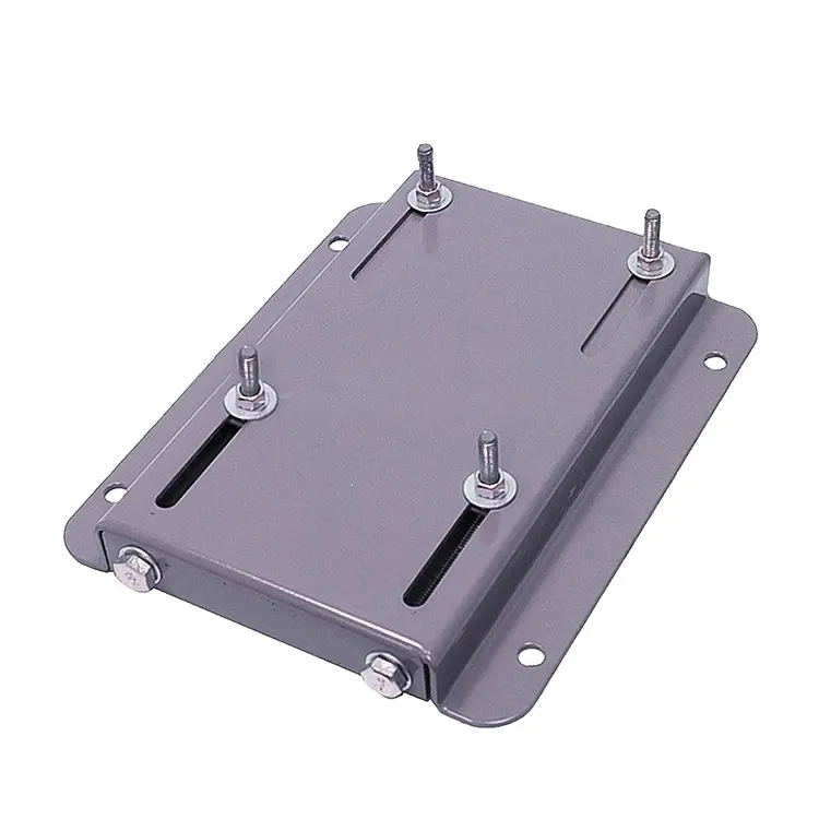
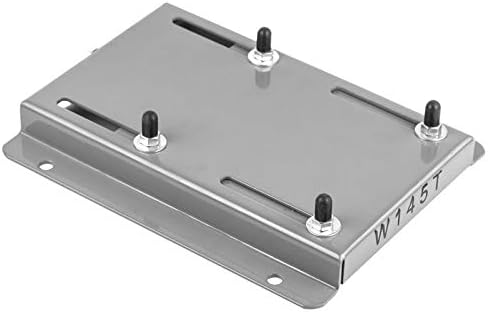
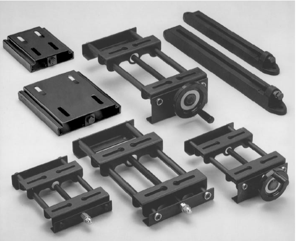
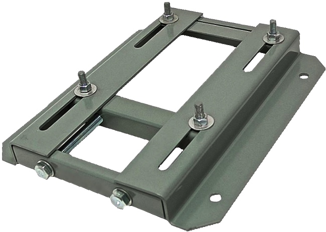
High Quality MP Series Motor Base For Large Power Motors
Motor bases series absorb the advanced technology home and abroad, integrated with characteristics of all kinds of motors. This product is made of high quality steel plate. It is suitable for different kinds of motors with compact structure, beautiful appearance, easy installation and flexible tension adjustment.
MP Motor Base
Galvanization finish, with monoplate sliding, bending and pressing
Fixing and adjustment of large power motors
Our door accessory factory is a professional and successful manufacturer of gate hardware which are used for sliding gate wheel, swing gate and cantilever gate wheel. By endless hard-working and innovation in the past years, our company has become the leading producer of this industry in China. We are backed by powerful technology and production, (high-speed) stamping machines, track making machines, wire cutting machines, milling machines, tooling making team, technical team, production staffs, aggressive management and sales team who has shown dedicated performance standards and made us experienced supplier to the international frontiers. To pursue market opportunity actively and meet the customer demands in great extent, our company keeps improving the products with more specifications and varieties. The marketing coverage is steadily expanding. Enjoying good reputation from all the customers worldwide, we are the reliable partner you can trust in China.
FAQ:
Q1: Are you trading company or manufacturer ?
A: We are factory.
Q2: How long is your delivery time and shipment?
1.Sample Lead-times: generally 10 workdays.
2.Production Lead-times: 15-20 workdays after getting your deposit.
Q3. What is your terms of payment?
A: T/T 30% as deposit, and 70% before delivery.
We’ll show you the photos of the products and packages before you pay the balance.
Q4: What is your advantages?
1. Manufacturer,the most competitive price and good quality.
2. Perfect technical engineers give you the best support.
3. OEM is available.
4. Rich stock and quick delivery.
Q5. If you can’t find the product on our website,what do you next?
Please send us inquiry with product pictures and drawings by email or other ways and we’ll check
| Condition: | New |
|---|---|
| Certification: | CE |
| Standard: | ANSI |
| Customized: | Customized |
| Material: | Steel |
| Application: | Metal Recycling Machine, Metal Cutting Machine, Metal Straightening Machinery, Metal Spinning Machinery, Metal forging Machinery, Metal Engraving Machinery, Metal Drawing Machinery |
| Samples: |
US$ 50/Piece
1 Piece(Min.Order) | |
|---|
| Customization: |
Available
|
|
|---|
Are there specific safety considerations associated with motor base installation?
Motor base installation involves specific safety considerations that should be taken into account. Here’s a detailed explanation:
1. Electrical Safety: When installing a motor base, it is crucial to ensure proper electrical safety measures. This includes disconnecting power sources, following lockout/tagout procedures, and wearing appropriate personal protective equipment (PPE) such as insulated gloves and safety glasses. It is important to work with qualified personnel who are knowledgeable about electrical safety practices.
2. Lifting and Rigging Safety: Motor bases can be heavy, especially when combined with the weight of the motor. During installation, it is essential to use proper lifting and rigging techniques to prevent accidents or injuries. This may involve using appropriate lifting equipment, such as cranes or hoists, and ensuring that the motor base is securely attached to the lifting apparatus.
3. Structural Integrity: Motor bases need to be properly installed on a stable and structurally sound foundation. Ensure that the mounting surface can support the weight of the motor and base without any risk of collapse or instability. If necessary, consult with a structural engineer to assess the adequacy of the installation site and make any required modifications.
4. Secure Fastening: Properly and securely fasten the motor base to the mounting surface using appropriate bolts, screws, or anchors. Follow the manufacturer’s recommendations for torque specifications to ensure secure fastening without overloading or damaging the base. Loose or inadequate fastening can lead to instability and potential accidents.
5. Ergonomics: Consider ergonomic factors during motor base installation to prevent strain or injury to personnel. Use proper lifting techniques, provide adequate lifting aids or equipment, and ensure that the work area is free from clutter or obstacles. This helps reduce the risk of musculoskeletal injuries during the installation process.
6. Environmental Hazards: Evaluate the installation site for any potential environmental hazards that could affect safety. This includes identifying and mitigating risks such as slippery surfaces, obstructions, or the presence of chemicals or hazardous materials. Take appropriate precautions to ensure a safe working environment for the installation personnel.
7. Manufacturer Guidelines: Follow the manufacturer’s guidelines and instructions for motor base installation. These guidelines often include specific safety considerations and precautions that are relevant to the particular motor base model. Adhering to the manufacturer’s recommendations helps ensure safe and proper installation.
8. Inspections and Testing: After the motor base installation, conduct thorough inspections and testing to verify the integrity of the installation and ensure proper functionality. This includes checking for any loose connections, verifying proper alignment, and performing electrical tests as required. Regular inspections and testing also play a crucial role in ongoing maintenance and safety of the motor base.
It is important to note that the specific safety considerations may vary depending on factors such as the size and type of motor, the installation site, and applicable regulations. It is recommended to consult with experts in motor base installation and adhere to relevant safety standards and guidelines to ensure a safe and compliant installation process.
What are the advancements or innovations in motor base technology?
The field of motor base technology has seen several advancements and innovations in recent years. Here’s a detailed explanation:
1. Smart Motor Bases: One significant advancement is the integration of smart technologies into motor bases. Smart motor bases incorporate sensors, connectivity features, and data analysis capabilities to monitor motor performance, detect anomalies, and provide real-time feedback. These bases can communicate with control systems, enabling predictive maintenance, energy optimization, and remote monitoring.
2. Vibration Control: Motor bases with enhanced vibration control features have emerged to address vibration-related challenges. These bases utilize advanced materials, design techniques, and vibration isolation technologies to minimize the transmission of motor vibrations to the surrounding structure. This helps reduce noise, prevent structural damage, and improve overall system performance.
3. Alignment Assistance: Advancements in alignment assistance have made motor base installation and alignment more efficient. Some motor bases now incorporate built-in alignment guides, laser alignment systems, or augmented reality-based alignment tools. These features assist technicians in achieving precise alignment, reducing installation time and minimizing the risk of misalignment-related issues.
4. Modular Design: Modular motor bases have gained popularity due to their flexibility and ease of installation. These bases consist of standardized modules that can be easily configured and combined to accommodate motors of various sizes and types. The modular design simplifies inventory management, reduces lead times, and allows for quick adaptation to changing motor requirements.
5. Energy Efficiency Enhancements: Motor bases are increasingly designed with energy efficiency in mind. Advancements in materials, construction techniques, and aerodynamics have led to motor bases with reduced energy losses and improved heat dissipation capabilities. Additionally, features like adjustable mounting slots, quick-release mechanisms, and integrated thermal management systems contribute to enhanced energy efficiency.
6. Environmental Considerations: Motor base technology has also evolved to address environmental concerns. Manufacturers are incorporating sustainable materials, optimizing designs for recyclability, and reducing the environmental footprint of motor bases. This includes using eco-friendly coatings, minimizing the use of hazardous substances, and implementing environmentally conscious manufacturing processes.
7. Integration with Condition Monitoring: Motor bases are being integrated with condition monitoring systems to enable proactive maintenance. By integrating sensors for temperature, vibration, and other relevant parameters, motor bases can provide real-time data on motor health. This data can be used to schedule maintenance tasks, detect early signs of failure, and optimize performance.
These advancements in motor base technology have led to improved motor performance, increased energy efficiency, enhanced reliability, and simplified maintenance procedures. As technology continues to advance, motor bases are expected to become even more intelligent, adaptable, and environmentally friendly.
What is the purpose of a motor base in industrial applications?
A motor base serves an important purpose in industrial applications. Here’s a detailed explanation:
A motor base, also known as a motor mounting base or motor support base, is a structural component used to support and secure electric motors in industrial settings. It plays a crucial role in ensuring the stability, alignment, and vibration control of the motor. Here are some key purposes of a motor base:
1. Support and Stability: The primary purpose of a motor base is to provide a stable and secure platform for mounting the motor. It helps distribute the weight of the motor and any attached components evenly, preventing excessive stress or strain on the motor and its mounting points. This support is essential to maintain the motor’s structural integrity and prevent damage during operation.
2. Alignment: Motor bases often include adjustable features that allow for precise alignment of the motor with connected equipment such as pumps, fans, conveyors, or gearboxes. Proper alignment is critical for efficient power transmission, minimizing wear and tear on the motor and the connected equipment, and reducing the risk of mechanical failures.
3. Vibration Control: Vibrations can adversely affect the performance and lifespan of an electric motor. A motor base helps dampen and control vibrations generated during motor operation, reducing the transmission of vibrations to the surrounding equipment or structure. This helps minimize noise, prevents damage to nearby components, and enhances overall system reliability.
4. Maintenance and Serviceability: Motor bases are designed to facilitate maintenance and service tasks. They often feature accessibility features such as removable panels or brackets that allow technicians to easily access the motor for inspections, repairs, or replacements. Motor bases also simplify the process of disconnecting and reconnecting motors during maintenance activities.
5. Adaptability: Motor bases are available in various sizes, configurations, and materials to accommodate different motor types and installation requirements. They can be customized or equipped with modular components to adapt to specific applications or environmental conditions. This flexibility allows for easier installation and integration of motors into industrial systems.
Motor bases are typically made of sturdy materials like steel or cast iron to provide strength and durability. They are designed to withstand the dynamic forces, vibrations, and environmental conditions encountered in industrial environments.
When installing a motor base, it’s important to follow manufacturer guidelines and ensure proper anchoring to the foundation or supporting structure. This helps maintain the integrity of the motor base and ensures the reliable operation of the motor.
In summary, the purpose of a motor base in industrial applications is to provide support, stability, alignment, vibration control, and facilitate maintenance for electric motors, contributing to the overall performance, longevity, and reliability of the motor and the systems it powers.
editor by CX 2023-11-18
China Bonfilioli Planetary Gear Motors with Great quality
Product Description
Solution Description
SGR planetary equipment motor
Technical data:
one. Ratio assortment: 8.1-191
two. Enter electrical power: .12-270 KW
3. Allow torque rang: ≤ 50000 N. M
4. Output velocity: .3~205 r/min
5. Structure: Foot-mounted, flange-mounted, shaft-mounted
| Enter composition | motor,IEC flange |
| Output velocity | motor,IEC flange,enter shaft |
| sound shaft, hollow shaft with essential,with shrink disk |
Characteristic:
one. Undertake optimized style, module mixture, correct angle output, space reduction
2. Substantial energy and longevity gears
three. Can be merged with numerous motors, wider ratio range
four. Massive output torque, efficiently startup, higher effectiveness
Generation photos:
———————————————————————————————————————————————
FAQ:
one.Are you a manufacturing unit or trader ?
We are a skilled manufacturing unit which has 20 years history specialised in equipment transmission .
2.MOQ:
Our MOQ is 1pcs. Nevertheless there is 1 managing cost $one hundred fifty for the single get which less than $3000.00
3. Guarantee
Our warranty is 12months
four. Payment phrase
a hundred% T/T in advance and LC at sight .
five. Do you acknowledge customization ?
Indeed.SGR have strong R&D staff, we can provide customizable service according to demands.
6. Packing
Typically we use normal export plywood scenario to set up the cargo .
7. Shipping time
In normal ,time of delivery is 30days soon after getting the prepayment .
8. What types of certification do you use ?
DNV-ISO9001:2008, SGS,CE and so forth, And new items patent.
nine. What types of inspection you do prior to cargo ?
We do temperature examination, sounds, and oil leak inspection and commissioning prior to shipment.
ten.How do you solve if the generation have problem ?
Mostly, we don’t need customer send out the products again to us. Since the price is quite high, if there satisfies a dilemma,we firstly ask for the pictures for ruined areas. And base on the photographs, we can have a basic notion for the defect reason. Our promise is twelve months, if throughout the guarantee, we can offer repair .
|
/ Piece | |
1 Piece (Min. Order) |
###
| Application: | Motor, Machinery |
|---|---|
| Function: | Distribution Power, Change Drive Torque, Speed Reduction |
| Layout: | Coaxial |
| Hardness: | Hardened Tooth Surface |
| Installation: | Vertical Type |
| Step: | Single-Step |
###
| Samples: |
US$ 200/Piece
1 Piece(Min.Order) |
|---|
###
| Customization: |
|---|
###
| Input structure | motor,IEC flange |
| Output speed | motor,IEC flange,input shaft |
| solid shaft, hollow shaft with key,with shrink disk |
Benefits of a Planetary Motor
Besides being one of the most efficient forms of a drive, a Planetary Motor also offers a great number of other benefits. These features enable it to create a vast range of gear reductions, as well as generate higher torques and torque density. Let’s take a closer look at the benefits this mechanism has to offer. To understand what makes it so appealing, we’ll explore the different types of planetary systems.
Solar gear
The solar gear on a planetary motor has two distinct advantages. It produces less noise and heat than a helical gear. Its compact footprint also minimizes noise. It can operate at high speeds without sacrificing efficiency. However, it must be maintained with constant care to operate efficiently. Solar gears can be easily damaged by water and other debris. Solar gears on planetary motors may need to be replaced over time.
A planetary gearbox is composed of a sun gear and two or more planetary ring and spur gears. The sun gear is the primary gear and is driven by the input shaft. The other two gears mesh with the sun gear and engage the stationary ring gear. The three gears are held together by a carrier, which sets the spacing. The output shaft then turns the planetary gears. This creates an output shaft that rotates.
Another advantage of planetary gears is that they can transfer higher torques while being compact. These advantages have led to the creation of solar gears. They can reduce the amount of energy consumed and produce more power. They also provide a longer service life. They are an excellent choice for solar-powered vehicles. But they must be installed by a certified solar energy company. And there are other advantages as well. When you install a solar gear on a planetary motor, the energy produced by the sun will be converted to useful energy.
A solar gear on a planetary motor uses a solar gear to transmit torque from the sun to the planet. This system works on the principle that the sun gear rotates at the same rate as the planet gears. The sun gear has a common design modulus of -Ns/Np. Hence, a 24-tooth sun gear equals a 3-1/2 planet gear ratio. When you consider the efficiency of solar gears on planetary motors, you will be able to determine whether the solar gears are more efficient.
Sun gear
The mechanical arrangement of a planetary motor comprises of two components: a ring gear and a sun gear. The ring gear is fixed to the motor’s output shaft, while the sun gear rolls around and orbits around it. The ring gear and sun gear are linked by a planetary carrier, and the torque they produce is distributed across their teeth. The planetary structure arrangement also reduces backlash, and is critical to achieve a quick start and stop cycle.
When the two planetary gears rotate independently, the sun gear will rotate counterclockwise and the ring-gear will turn in the same direction. The ring-gear assembly is mounted in a carrier. The carrier gear and sun gear are connected to each other by a shaft. The planetary gears and sun gear rotate around each other on the ring-gear carrier to reduce the speed of the output shaft. The planetary gear system can be multiplied or staged to obtain a higher reduction ratio.
A planetary gear motor mimics the planetary rotation system. The input shaft turns a central gear, known as the sun gear, while the planetary gears rotate around a stationary sun gear. The motor’s compact design allows it to be easily mounted to a vehicle, and its low weight makes it ideal for small vehicles. In addition to being highly efficient, a planetary gear motor also offers many other benefits.
A planetary gearbox uses a sun gear to provide torque to the other gears. The planet pinions mesh with an internal tooth ring gear to generate rotation. The carrier also acts as a hub between the input gear and output shaft. The output shaft combines these two components, giving a higher torque. There are three types of planetary gearboxes: the sun gear and a wheel drive planetary gearbox.
Planetary gear
A planetary motor gear works by distributing rotational force along a separating plate and a cylindrical shaft. A shock-absorbing device is included between the separating plate and cylindrical shaft. This depressed portion prevents abrasion wear and foreign particles from entering the device. The separating plate and shaft are positioned coaxially. In this arrangement, the input shaft and output shaft are rotated relative to one another. The rotatable disc absorbs the impact.
Another benefit of a planetary motor gear is its efficiency. Planetary motor gears are highly efficient at transferring power, with 97% of the input energy being transferred to the output. They can also have high gear ratios, and offer low noise and backlash. This design also allows the planetary gearbox to work with electric motors. In addition, planetary gears also have a long service life. The efficiency of planetary gears is due in part to the large number of teeth.
Other benefits of a planetary motor gear include the ease of changing ratios, as well as the reduced safety stock. Unlike other gears, planetary gears don’t require special tools for changing ratios. They are used in numerous industries, and share parts across multiple sizes. This means that they are cost-effective to produce and require less safety stock. They can withstand high shock and wear, and are also compact. If you’re looking for a planetary motor gear, you’ve come to the right place.
The axial end surface of a planetary gear can be worn down by abrasion with a separating plate. In addition, foreign particles may enter the planetary gear device. These particles can damage the gears or even cause noise. As a result, you should check planetary gears for damage and wear. If you’re looking for a gear, make sure it has been thoroughly tested and installed by a professional.
Planetary gearbox
A planetary motor and gearbox are a common combination of electric and mechanical power sources. They share the load of rotation between multiple gear teeth to increase the torque capacity. This design is also more rigid, with low backlash that can be as low as one or two arc minutes. The advantages of a planetary gearmotor over a conventional electric motor include compact size, high efficiency, and less risk of gear failure. Planetary gear motors are also more reliable and durable than conventional electric motors.
A planetary gearbox is designed for a single stage of reduction, or a multiple-stage unit can be built with several individual cartridges. Gear ratios may also be selected according to user preference, either to face mount the output stage or to use a 5mm hex shaft. For multi-stage planetary gearboxes, there are a variety of different options available. These include high-efficiency planetary gearboxes that achieve a 98% efficiency at single reduction. In addition, they are noiseless, and reduce heat loss.
A planetary gearbox may be used to increase torque in a robot or other automated system. There are different types of planetary gear sets available, including gearboxes with sliding or rolling sections. When choosing a planetary gearset, consider the environment and other factors such as backlash, torque, and ratio. There are many advantages to a planetary gearbox and the benefits and drawbacks associated with it.
Planetary gearboxes are similar to those in a solar system. They feature a central sun gear in the middle, two or more outer gears, and a ring gear at the output. The planetary gears rotate in a ring-like structure around a stationary sun gear. When the gears are engaged, they are connected by a carrier that is fixed to the machine’s shaft.
Planetary gear motor
Planetary gear motors reduce the rotational speed of an armature by one or more times. The reduction ratio depends on the structure of the planetary gear device. The planetary gear device has an output shaft and an armature shaft. A separating plate separates the two. The output shaft moves in a circular pattern to turn the pinion 3. When the pinion rotates to the engagement position, it is engaged with the ring gear 4. The ring gear then transmits the rotational torque to the armature shaft. The result is that the engine cranks up.
Planetary gear motors are cylindrical in shape and are available in various power levels. They are typically made of steel or brass and contain multiple gears that share the load. These motors can handle massive power transfers. The planetary gear drive, on the other hand, requires more components, such as a sun’s gear and multiple planetary gears. Consequently, it may not be suitable for all types of applications. Therefore, the planetary gear drive is generally used for more complex machines.
Brush dusts from the electric motor may enter the planetary gear device and cause it to malfunction. In addition, abrasion wear on the separating plate can affect the gear engagement of the planetary gear device. If this occurs, the gears will not engage properly and may make noise. In order to prevent such a situation from occurring, it is important to regularly inspect planetary gear motors and their abrasion-resistant separating plates.
Planetary gear motors come in many different power levels and sizes. These motors are usually cylindrical in shape and are made of steel, brass, plastic, or a combination of both materials. A planetary gear motor can be used in applications where space is an issue. This motor also allows for low gearings in small spaces. The planetary gearing allows for large amounts of power transfer. The output shaft size is dependent on the gear ratio and the motor speed.
editor by CX 2023-03-28
China SANJING MOT D240 42kw Helicopter Biggest King-size Man Size Mad Manned Gigante Brushless Per Drone Motors manufacturer
Error:获取返回内容失败,
Your session has expired. Please reauthenticate.
Dynamic Modeling of a Planetary Motor
A planetary gear motor consists of a series of gears rotating in perfect synchrony, allowing them to deliver torque in a higher output capacity than a spur gear motor. Unlike the planetary motor, spur gear motors are simpler to build and cost less, but they are better for applications requiring lower torque output. That is because each gear carries the entire load. The following are some key differences between the two types of gearmotors.
planetary gear system
A planetary gear transmission is a type of gear mechanism that transfers torque from one source to another, usually a rotary motion. Moreover, this type of gear transmission requires dynamic modeling to investigate its durability and reliability. Previous studies included both uncoupled and coupled meshing models for the analysis of planetary gear transmission. The combined model considers both the shaft structural stiffness and the bearing support stiffness. In some applications, the flexible planetary gear may affect the dynamic response of the system.
In a planetary gear device, the axial end surface of the cylindrical portion is rotatable relative to the separating plate. This mechanism retains lubricant. It is also capable of preventing foreign particles from entering the planetary gear system. A planetary gear device is a great choice if your planetary motor’s speed is high. A high-quality planetary gear system can provide a superior performance than conventional systems.
A planetary gear system is a complex mechanism, involving three moving links that are connected to each other through joints. The sun gear acts as an input and the planet gears act as outputs. They rotate about their axes at a ratio determined by the number of teeth on each gear. The sun gear has 24 teeth, while the planet gears have three-quarters that ratio. This ratio makes a planetary motor extremely efficient.
planetary gear train
To predict the free vibration response of a planetary motor gear train, it is essential to develop a mathematical model for the system. Previously, static and dynamic models were used to study the behavior of planetary motor gear trains. In this study, a dynamic model was developed to investigate the effects of key design parameters on the vibratory response. Key parameters for planetary gear transmissions include the structure stiffness and mesh stiffness, and the mass and location of the shaft and bearing supports.
The design of the planetary motor gear train consists of several stages that can run with variable input speeds. The design of the gear train enables the transmission of high torques by dividing the load across multiple planetary gears. In addition, the planetary gear train has multiple teeth which mesh simultaneously in operation. This design also allows for higher efficiency and transmittable torque. Here are some other advantages of planetary motor gear trains. All these advantages make planetary motor gear trains one of the most popular types of planetary motors.
The compact footprint of planetary gears allows for excellent heat dissipation. High speeds and sustained performances will require lubrication. This lubricant can also reduce noise and vibration. But if these characteristics are not desirable for your application, you can choose a different gear type. Alternatively, if you want to maintain high performance, a planetary motor gear train will be the best choice. So, what are the advantages of planetary motor gears?
planetary gear train with fixed carrier train ratio
The planetary gear train is a common type of transmission in various machines. Its main advantages are high efficiency, compactness, large transmission ratio, and power-to-weight ratio. This type of gear train is a combination of spur gears, single-helical gears, and herringbone gears. Herringbone planetary gears have lower axial force and high load carrying capacity. Herringbone planetary gears are commonly used in heavy machinery and transmissions of large vehicles.
To use a planetary gear train with a fixed carrier train ratio, the first and second planets must be in a carrier position. The first planet is rotated so that its teeth mesh with the sun’s. The second planet, however, cannot rotate. It must be in a carrier position so that it can mesh with the sun. This requires a high degree of precision, so the planetary gear train is usually made of multiple sets. A little analysis will simplify this design.
The planetary gear train is made up of three components. The outer ring gear is supported by a ring gear. Each gear is positioned at a specific angle relative to one another. This allows the gears to rotate at a fixed rate while transferring the motion. This design is also popular in bicycles and other small vehicles. If the planetary gear train has several stages, multiple ring gears may be shared. A stationary ring gear is also used in pencil sharpener mechanisms. Planet gears are extended into cylindrical cutters. The ring gear is stationary and the planet gears rotate around a sun axis. In the case of this design, the outer ring gear will have a -3/2 planet gear ratio.
planetary gear train with zero helix angle
The torque distribution in a planetary gear is skewed, and this will drastically reduce the load carrying capacity of a needle bearing, and therefore the life of the bearing. To better understand how this can affect a gear train, we will examine two studies conducted on the load distribution of a planetary gear with a zero helix angle. The first study was done with a highly specialized program from the bearing manufacturer INA/FAG. The red line represents the load distribution along a needle roller in a zero helix gear, while the green line corresponds to the same distribution of loads in a 15 degree helix angle gear.
Another method for determining a gear’s helix angle is to consider the ratio of the sun and planet gears. While the sun gear is normally on the input side, the planet gears are on the output side. The sun gear is stationary. The two gears are in engagement with a ring gear that rotates 45 degrees clockwise. Both gears are attached to pins that support the planet gears. In the figure below, you can see the tangential and axial gear mesh forces on a planetary gear train.
Another method used for calculating power loss in a planetary gear train is the use of an auto transmission. This type of gear provides balanced performance in both power efficiency and load capacity. Despite the complexities, this method provides a more accurate analysis of how the helix angle affects power loss in a planetary gear train. If you’re interested in reducing the power loss of a planetary gear train, read on!
planetary gear train with spur gears
A planetary gearset is a type of mechanical drive system that uses spur gears that move in opposite directions within a plane. Spur gears are one of the more basic types of gears, as they don’t require any specialty cuts or angles to work. Instead, spur gears use a complex tooth shape to determine where the teeth will make contact. This in turn, will determine the amount of power, torque, and speed they can produce.
A two-stage planetary gear train with spur gears is also possible to run at variable input speeds. For such a setup, a mathematical model of the gear train is developed. Simulation of the dynamic behaviour highlights the non-stationary effects, and the results are in good agreement with the experimental data. As the ratio of spur gears to spur gears is not constant, it is called a dedendum.
A planetary gear train with spur gears is a type of epicyclic gear train. In this case, spur gears run between gears that contain both internal and external teeth. The circumferential motion of the spur gears is analogous to the rotation of planets in the solar system. There are four main components of a planetary gear train. The planet gear is positioned inside the sun gear and rotates to transfer motion to the sun gear. The planet gears are mounted on a joint carrier that is connected to the output shaft.
planetary gear train with helical gears
A planetary gear train with helical teeth is an extremely powerful transmission system that can provide high levels of power density. Helical gears are used to increase efficiency by providing a more efficient alternative to conventional worm gears. This type of transmission has the potential to improve the overall performance of a system, and its benefits extend far beyond the power density. But what makes this transmission system so appealing? What are the key factors to consider when designing this type of transmission system?
The most basic planetary train consists of the sun gear, planet gear, and ring gear elements. The number of planets varies, but the basic structure of planetary gears is similar. A simple planetary geartrain has the sun gear driving a carrier assembly. The number of planets can be as low as two or as high as six. A planetary gear train has a low mass inertia and is compact and reliable.
The mesh phase properties of a planetary gear train are particularly important in designing the profiles. Various parameters such as mesh phase difference and tooth profile modifications must be studied in depth in order to fully understand the dynamic characteristics of a PGT. These factors, together with others, determine the helical gears’ performance. It is therefore essential to understand the mesh phase of a planetary gear train to design it effectively.
editor by czh 2023-02-20
China High Efficiency Permanent Magnet Synchronous Motor PMSM 3 Phase AC Motors motorbase
Warranty: 3years
Model Number: HCTY132M-4L
Type: Asynchronous Motor
Frequency: 50Hz
Phase: Three-phase
Protect Feature: Waterproof
AC Voltage: 380V
Efficiency: IE 4
Product Name: AC Motors
Working Mode: S1
Cooling Mode: IC411
Enclosure Protection Grade: IP54
Rated Voltage: 380V or customized
Efficiency Idex: > 92%
High Power factor: Almost 1
Large Starting Torgue: 2 times than others
Range of frequency: > 1:1000
Advantage: Small, light, low noise, etc
Packaging Details: Export standard box with magnets isolation for High Efficiency Permanent Magnet Synchronous Motor PMSM 3 Phase AC Motors
Port: HangZhou
The Permanent Magnet Synchronous Motor PMSM 3 Phase AC Motors efficiency index reached level 2 or above of 3 0571 -2013.This series of products can completely replace Y series low-voltage asynchronous motors, widely used in petrochemical, mining, textile and other working conditions.
| Product Name | Permanent Magnet Synchronous Motor PMSM 3 Phase AC Motors |
| Item No. | HCTY225M-6 |
| Rated Output | 30KW |
| Rated Voltage | 380V or customized |
| Rated Current | 49.0A |
| Efficiency Idex | > 92% |
| Poles | 6 |
| Power Factor | 0.98cos |
| Frequency | 50Hz |
| Speed | 1000r/min |
| Rated Torque | 286.5N.m |
| High Power factor | Almost 1 |
| Large Starting Torgue | 2 times than others |
| Range of frequency | > 1:1000 |
| Working Mode | S1 |
| Cooling Mode | IC411 |
| Enclosure Protection Grade | IP54 |
| Advantage | Small, light, low noise, etc |
Benefits of a Planetary Motor
Besides being one of the most efficient forms of a drive, a Planetary Motor also offers a great number of other benefits. These features enable it to create a vast range of gear reductions, as well as generate higher torques and torque density. Let’s take a closer look at the benefits this mechanism has to offer. To understand what makes it so appealing, we’ll explore the different types of planetary systems.
Solar gear
The solar gear on a planetary motor has two distinct advantages. It produces less noise and heat than a helical gear. Its compact footprint also minimizes noise. It can operate at high speeds without sacrificing efficiency. However, it must be maintained with constant care to operate efficiently. Solar gears can be easily damaged by water and other debris. Solar gears on planetary motors may need to be replaced over time.
A planetary gearbox is composed of a sun gear and two or more planetary ring and spur gears. The sun gear is the primary gear and is driven by the input shaft. The other two gears mesh with the sun gear and engage the stationary ring gear. The three gears are held together by a carrier, which sets the spacing. The output shaft then turns the planetary gears. This creates an output shaft that rotates.
Another advantage of planetary gears is that they can transfer higher torques while being compact. These advantages have led to the creation of solar gears. They can reduce the amount of energy consumed and produce more power. They also provide a longer service life. They are an excellent choice for solar-powered vehicles. But they must be installed by a certified solar energy company. And there are other advantages as well. When you install a solar gear on a planetary motor, the energy produced by the sun will be converted to useful energy.
A solar gear on a planetary motor uses a solar gear to transmit torque from the sun to the planet. This system works on the principle that the sun gear rotates at the same rate as the planet gears. The sun gear has a common design modulus of -Ns/Np. Hence, a 24-tooth sun gear equals a 3-1/2 planet gear ratio. When you consider the efficiency of solar gears on planetary motors, you will be able to determine whether the solar gears are more efficient.
Sun gear
The mechanical arrangement of a planetary motor comprises of two components: a ring gear and a sun gear. The ring gear is fixed to the motor’s output shaft, while the sun gear rolls around and orbits around it. The ring gear and sun gear are linked by a planetary carrier, and the torque they produce is distributed across their teeth. The planetary structure arrangement also reduces backlash, and is critical to achieve a quick start and stop cycle.
When the two planetary gears rotate independently, the sun gear will rotate counterclockwise and the ring-gear will turn in the same direction. The ring-gear assembly is mounted in a carrier. The carrier gear and sun gear are connected to each other by a shaft. The planetary gears and sun gear rotate around each other on the ring-gear carrier to reduce the speed of the output shaft. The planetary gear system can be multiplied or staged to obtain a higher reduction ratio.
A planetary gear motor mimics the planetary rotation system. The input shaft turns a central gear, known as the sun gear, while the planetary gears rotate around a stationary sun gear. The motor’s compact design allows it to be easily mounted to a vehicle, and its low weight makes it ideal for small vehicles. In addition to being highly efficient, a planetary gear motor also offers many other benefits.
A planetary gearbox uses a sun gear to provide torque to the other gears. The planet pinions mesh with an internal tooth ring gear to generate rotation. The carrier also acts as a hub between the input gear and output shaft. The output shaft combines these two components, giving a higher torque. There are three types of planetary gearboxes: the sun gear and a wheel drive planetary gearbox.
Planetary gear
A planetary motor gear works by distributing rotational force along a separating plate and a cylindrical shaft. A shock-absorbing device is included between the separating plate and cylindrical shaft. This depressed portion prevents abrasion wear and foreign particles from entering the device. The separating plate and shaft are positioned coaxially. In this arrangement, the input shaft and output shaft are rotated relative to one another. The rotatable disc absorbs the impact.
Another benefit of a planetary motor gear is its efficiency. Planetary motor gears are highly efficient at transferring power, with 97% of the input energy being transferred to the output. They can also have high gear ratios, and offer low noise and backlash. This design also allows the planetary gearbox to work with electric motors. In addition, planetary gears also have a long service life. The efficiency of planetary gears is due in part to the large number of teeth.
Other benefits of a planetary motor gear include the ease of changing ratios, as well as the reduced safety stock. Unlike other gears, planetary gears don’t require special tools for changing ratios. They are used in numerous industries, and share parts across multiple sizes. This means that they are cost-effective to produce and require less safety stock. They can withstand high shock and wear, and are also compact. If you’re looking for a planetary motor gear, you’ve come to the right place.
The axial end surface of a planetary gear can be worn down by abrasion with a separating plate. In addition, foreign particles may enter the planetary gear device. These particles can damage the gears or even cause noise. As a result, you should check planetary gears for damage and wear. If you’re looking for a gear, make sure it has been thoroughly tested and installed by a professional.
Planetary gearbox
A planetary motor and gearbox are a common combination of electric and mechanical power sources. They share the load of rotation between multiple gear teeth to increase the torque capacity. This design is also more rigid, with low backlash that can be as low as one or two arc minutes. The advantages of a planetary gearmotor over a conventional electric motor include compact size, high efficiency, and less risk of gear failure. Planetary gear motors are also more reliable and durable than conventional electric motors.
A planetary gearbox is designed for a single stage of reduction, or a multiple-stage unit can be built with several individual cartridges. Gear ratios may also be selected according to user preference, either to face mount the output stage or to use a 5mm hex shaft. For multi-stage planetary gearboxes, there are a variety of different options available. These include high-efficiency planetary gearboxes that achieve a 98% efficiency at single reduction. In addition, they are noiseless, and reduce heat loss.
A planetary gearbox may be used to increase torque in a robot or other automated system. There are different types of planetary gear sets available, including gearboxes with sliding or rolling sections. When choosing a planetary gearset, consider the environment and other factors such as backlash, torque, and ratio. There are many advantages to a planetary gearbox and the benefits and drawbacks associated with it.
Planetary gearboxes are similar to those in a solar system. They feature a central sun gear in the middle, two or more outer gears, and a ring gear at the output. The planetary gears rotate in a ring-like structure around a stationary sun gear. When the gears are engaged, they are connected by a carrier that is fixed to the machine’s shaft.
Planetary gear motor
Planetary gear motors reduce the rotational speed of an armature by one or more times. The reduction ratio depends on the structure of the planetary gear device. The planetary gear device has an output shaft and an armature shaft. A separating plate separates the two. The output shaft moves in a circular pattern to turn the pinion 3. When the pinion rotates to the engagement position, it is engaged with the ring gear 4. The ring gear then transmits the rotational torque to the armature shaft. The result is that the engine cranks up.
Planetary gear motors are cylindrical in shape and are available in various power levels. They are typically made of steel or brass and contain multiple gears that share the load. These motors can handle massive power transfers. The planetary gear drive, on the other hand, requires more components, such as a sun’s gear and multiple planetary gears. Consequently, it may not be suitable for all types of applications. Therefore, the planetary gear drive is generally used for more complex machines.
Brush dusts from the electric motor may enter the planetary gear device and cause it to malfunction. In addition, abrasion wear on the separating plate can affect the gear engagement of the planetary gear device. If this occurs, the gears will not engage properly and may make noise. In order to prevent such a situation from occurring, it is important to regularly inspect planetary gear motors and their abrasion-resistant separating plates.
Planetary gear motors come in many different power levels and sizes. These motors are usually cylindrical in shape and are made of steel, brass, plastic, or a combination of both materials. A planetary gear motor can be used in applications where space is an issue. This motor also allows for low gearings in small spaces. The planetary gearing allows for large amounts of power transfer. The output shaft size is dependent on the gear ratio and the motor speed.
editor by czh2023-02-09
China High Efficiency Permanent Magnet Synchronous Motor PMSM 3 Phase AC Motors with Hot selling
Warranty: 3years
Model Number: HCTY132M-4L
Type: Asynchronous Motor
Frequency: 50Hz
Phase: Three-phase
Protect Feature: Waterproof
AC Voltage: 380V
Efficiency: IE 4
Product Name: AC Motors
Working Mode: S1
Cooling Mode: IC411
Enclosure Protection Grade: IP54
Rated Voltage: 380V or customized
Efficiency Idex: > 92%
High Power factor: Almost 1
Large Starting Torgue: 2 times than others
Range of frequency: > 1:1000
Advantage: Small, light, low noise, etc
Packaging Details: Export standard box with magnets isolation for High Efficiency Permanent Magnet Synchronous Motor PMSM 3 Phase AC Motors
Port: HangZhou
The Permanent Magnet Synchronous Motor PMSM 3 Phase AC Motors efficiency index reached level 2 or above of 3 0571 -2013.This series of products can completely replace Y series low-voltage asynchronous motors, widely used in petrochemical, mining, textile and other working conditions.
| Product Name | Permanent Magnet Synchronous Motor PMSM 3 Phase AC Motors |
| Item No. | HCTY225M-6 |
| Rated Output | 30KW |
| Rated Voltage | 380V or customized |
| Rated Current | 49.0A |
| Efficiency Idex | > 92% |
| Poles | 6 |
| Power Factor | 0.98cos |
| Frequency | 50Hz |
| Speed | 1000r/min |
| Rated Torque | 286.5N.m |
| High Power factor | Almost 1 |
| Large Starting Torgue | 2 times than others |
| Range of frequency | > 1:1000 |
| Working Mode | S1 |
| Cooling Mode | IC411 |
| Enclosure Protection Grade | IP54 |
| Advantage | Small, light, low noise, etc |
The Basics of a Gear Motor
The basic mechanism behind the gear motor is the principle of conservation of angular momentum. The smaller the gear, the more RPM it covers and the larger the gear, the more torque it produces. The ratio of angular velocity of two gears is called the gear ratio. Moreover, the same principle applies to multiple gears. This means that the direction of rotation of each adjacent gear is always the opposite of the one it is attached to.
Induction worm gear motor
If you’re looking for an electric motor that can deliver high torque, an Induction worm gear motor might be the right choice. This type of motor utilizes a worm gear attached to the motor to rotate a main gear. Because this type of motor is more efficient than other types of motors, it can be used in applications requiring massive reduction ratios, as it is able to provide more torque at a lower speed.
The worm gear motor is designed with a spiral shaft that is set into splines in another gear. The speed at which the worm gear rotates is dependent on the torque produced by the main gear. Induction worm gear motors are best suited for use in low-voltage applications such as electric cars, renewable energy systems, and industrial equipment. They come with a wide range of power-supply options, including twelve-volt, 24-volt, and 36-volt AC power supplies.
These types of motors can be used in many industrial settings, including elevators, airport equipment, food packaging facilities, and more. They also produce less noise than other types of motors, which makes them a popular choice for manufacturers with limited space. The efficiency of worm gearmotors makes them an excellent choice for applications where noise is an issue. Induction worm gear motors can be compact and extremely high-torque.
While the Induction worm gear motor is most widely used in industrial applications, there are other kinds of gearmotors available. Some types are more efficient than others, and some are more expensive than others. For your application, choosing the correct motor and gearbox combination is crucial to achieving the desired result. You’ll find that the Induction worm gear motor is an excellent choice for many applications. The benefits of an Induction worm gear motor can’t be overstated.
The DC gear motor is an excellent choice for high-end industrial applications. This type of gearmotor is smaller and lighter than a standard AC motor and can deliver up to 200 watts of torque. A gear ratio of three to two can be found in these motors, which makes them ideal for a wide range of applications. A high-quality DC gear motor is a great choice for many industrial applications, as they can be highly efficient and provide a high level of reliability.
Electric gear motors are a versatile and widely used type of electric motor. Nevertheless, there are some applications that don’t benefit from them, such as applications with high shaft speed and low torque. Applications such as fan motors, pump and scanning machines are examples of such high-speed and high-torque demands. The most important consideration when choosing a gearmotor is its efficiency. Choosing the right size will ensure the motor runs efficiently at peak efficiency and will last for years.
Parallel shaft helical gear motor
The FC series parallel shaft helical gearmotor is a compact, lightweight, and high-performance unit that utilizes a parallel shaft structure. Its compact design is complemented by high transmission efficiency and high carrying capacity. The motor’s material is 20CrMnTi alloy steel. The unit comes with either a flanged input or bolt-on feet for installation. Its low noise and compact design make it an ideal choice for a variety of applications.
The helical gears are usually arranged in two rows of one another. Each row contains one or more rows of teeth. The parallel row has the teeth in a helical pattern, while the helical rows are lined up parallelly. In addition to this, the cross helical gears have a point contact design and do not overlap. They can be either parallel or crossed. The helical gear motors can have any number of helical pairs, each with a different pitch circle diameter.
The benefits of the Parallel Shaft Helical Gearbox include high temperature and pressure handling. It is produced by skilled professionals using cutting-edge technology, and is widely recognized for its high performance. It is available in a range of technical specifications and is custom-made to suit individual requirements. These gearboxes are durable and low-noise and feature high reliability. You can expect to save up to 40% of your energy by using them.
The parallel shaft helical gear motors are designed to reduce the speed of a rotating part. The nodular cast iron housing helps make the unit robust in difficult environments, while the precision-machined gears provide quiet, vibration-free operation. These motors are available in double reduction, triple reduction, and quadruple reduction. The capacity ranges from 0.12 kW to 45 kW. You can choose from a wide variety of capacities, depending on the size of your gearing needs.
The SEW-EURODRIVE parallel shaft helical gearmotor is a convenient solution for space-constrained applications. The machine’s modular design allows for easy mounting and a wide range of ambient temperatures. They are ideal for a variety of mechanical applications, including conveyors, augers, and more. If you want a small footprint, the SEW-EURODRIVE parallel shaft helical gear motor is the best solution for you.
The parallel shaft helical gears are advantageous for both high and low speed applications. Parallel helical gears are also suitable for low speed and low duty applications. A good example of a cross-helix gear is the oil pump of an internal combustion engine. Both types of helical gears are highly reliable and offer vibration-free operation. They are more costly than conventional gear motors, but offer more durability and efficiency.
Helical gear unit
This helical gear unit is designed to operate under a variety of demanding conditions and can be used in a wide range of applications. Designed for long life and high torque density, this gear unit is available in a variety of torques and gear ratios. Its design and construction make it compatible with a wide range of critical mechanical systems. Common applications include conveyors, material handling, steel mills, and paper mills.
Designed for high-performance applications, the Heidrive helical gear unit provides superior performance and value. Its innovative design allows it to function well under a wide range of operating conditions and is highly resistant to damage. These gear motors can be easily combined with a helical gear unit. Their combined power output is 100 Nm, and they have a high efficiency of up to 90%. For more information about the helical gear motor, contact a Heidrive representative.
A helical gear unit can be classified by its reference section in the standard plane or the turning plane. Its center gap is the same as that of a spur gear, and its number of teeth is the same. In addition to this, the helical gear has a low axial thrust, which is another important characteristic. The helical gear unit is more efficient at transferring torque than a spur gear, and it is quieter, too.
These units are designed to handle large loads. Whether you are using them for conveyors, augers, or for any other application that involves high-speed motion, a helical gear unit will deliver maximum performance. A helical gear unit from Flender can handle 400,000 tasks with a high degree of reliability. Its high efficiency and high resistance to load ensures high plant availability. These gear motors are available in a variety of sizes, from single-speed to multi-speed.
PEC geared motors benefit from decades of design experience and high quality materials. They are robust, quiet, and offer excellent performance. They are available in multiple configurations and are dimensionally interchangeable with other major brands. The gear motors are manufactured as modular kits to minimize inventory. They can be fitted with additional components, such as backstops and fans. This makes it easy to customize your gear motors and save money while reducing costs.
Another type of helical gears is the double helical gear. The double helical gear unit has two helical faces with a gap between them. They are better for enclosed gear systems as they provide greater tooth overlap and smoother performance. Compared to double helical gears, they are smaller and more flexible than the Herringbone type. So, if you’re looking for a gear motor, a helical gear unit may be perfect for you.
editor by czh2023-02-08
China Blince During High Efficiency Omp 400-2-a-D-B Planetary Wheel Drives Motor / Orbit Motors motor efficiency
Item Description
CZPT Hydro motors OMP460881365
| Type | OMP36 | OMP50 | OMP80 | OMP100 | OMP125 | OMP160 | OMP200 | OMP250 | OMP315 |
OMP400 | OMP500 | |||
| Displacement &lparcc&solrev) |
36 | 51.7 | seventy seven.7 | 96.two | 120.two | 157.2 | 194.five | 240.three | 314.five | 389.five | 486.5 | |||
| Max torque &lparn.m) |
cont | 55 | 100 | 146 | 182 | 236 | 302 | 360 | 460 | 475 | 490 | 430 | ||
| int | seventy six | 128 | 186 | 227 | 290 | 370 | 440 | 570 | 555 | 580 | 430 | |||
| Max pressure &lparMpa) |
cont | twelve.five | 14 | fourteen | fourteen | fourteen | fourteen | fourteen | 14 | 9. | 7. | 7. | ||
| int | sixteen.five | 17.five | seventeen.5 | 17.five | seventeen.5 | 17.5 | seventeen.5 | seventeen.5 | 14 | eleven.five | 9. | |||
| Max speed fee &lparrpm) |
cont | 1500 | 1150 | 770 | 615 | 490 | 383 | 310 | 250 | 192 | a hundred and fifty five | 120 | ||
| int | 1650 | 1450 | 960 | 770 | 615 | 475 | 385 | 310 | 240 | one hundred ninety | 150 | |||
| Max flow &lparL&solmin) |
cont | 55 | 60 | sixty | 60 | 60 | sixty | sixty | 60 | sixty | sixty | 60 | ||
| int | 60 | 75 | seventy five | 75 | 75 | 75 | 75 | 75 | 75 | seventy five | 75 | |||
| Weight &lparkg) |
5.6 | six | 5.seven | 5.nine | 6. | six.2 | 6.4 | 7. | 6.nine | 7.4 | 8. | |||
|
US $1 / Piece | |
1 Piece (Min. Order) |
###
| Number of Poles: | 4 |
|---|---|
| Type: | Hydraulic Motor |
| Displacement(Cc/Rev): | 389.5 |
| Continuous Max Speed(Rpm): | 155 |
| Continuous Max Torque(N.M): | 490 |
| Flange: | Standard 2 Hole Diamond Flange |
###
| Customization: |
Available
|
|---|
###
| Type | OMP36 | OMP50 | OMP80 | OMP100 | OMP125 | OMP160 | OMP200 | OMP250 | OMP315 |
OMP400 | OMP500 | |||
| Displacement (cc/rev) |
36 | 51.7 | 77.7 | 96.2 | 120.2 | 157.2 | 194.5 | 240.3 | 314.5 | 389.5 | 486.5 | |||
| Max torque (n.m) |
cont | 55 | 100 | 146 | 182 | 236 | 302 | 360 | 460 | 475 | 490 | 430 | ||
| int | 76 | 128 | 186 | 227 | 290 | 370 | 440 | 570 | 555 | 580 | 430 | |||
| Max pressure (Mpa) |
cont | 12.5 | 14 | 14 | 14 | 14 | 14 | 14 | 14 | 9.0 | 7.0 | 7.0 | ||
| int | 16.5 | 17.5 | 17.5 | 17.5 | 17.5 | 17.5 | 17.5 | 17.5 | 14 | 11.5 | 9.0 | |||
| Max speed rate (rpm) |
cont | 1500 | 1150 | 770 | 615 | 490 | 383 | 310 | 250 | 192 | 155 | 120 | ||
| int | 1650 | 1450 | 960 | 770 | 615 | 475 | 385 | 310 | 240 | 190 | 150 | |||
| Max flow (L/min) |
cont | 55 | 60 | 60 | 60 | 60 | 60 | 60 | 60 | 60 | 60 | 60 | ||
| int | 60 | 75 | 75 | 75 | 75 | 75 | 75 | 75 | 75 | 75 | 75 | |||
| Weight (kg) |
5.6 | 6 | 5.7 | 5.9 | 6.0 | 6.2 | 6.4 | 7.0 | 6.9 | 7.4 | 8.0 | |||
|
US $1 / Piece | |
1 Piece (Min. Order) |
###
| Number of Poles: | 4 |
|---|---|
| Type: | Hydraulic Motor |
| Displacement(Cc/Rev): | 389.5 |
| Continuous Max Speed(Rpm): | 155 |
| Continuous Max Torque(N.M): | 490 |
| Flange: | Standard 2 Hole Diamond Flange |
###
| Customization: |
Available
|
|---|
###
| Type | OMP36 | OMP50 | OMP80 | OMP100 | OMP125 | OMP160 | OMP200 | OMP250 | OMP315 |
OMP400 | OMP500 | |||
| Displacement (cc/rev) |
36 | 51.7 | 77.7 | 96.2 | 120.2 | 157.2 | 194.5 | 240.3 | 314.5 | 389.5 | 486.5 | |||
| Max torque (n.m) |
cont | 55 | 100 | 146 | 182 | 236 | 302 | 360 | 460 | 475 | 490 | 430 | ||
| int | 76 | 128 | 186 | 227 | 290 | 370 | 440 | 570 | 555 | 580 | 430 | |||
| Max pressure (Mpa) |
cont | 12.5 | 14 | 14 | 14 | 14 | 14 | 14 | 14 | 9.0 | 7.0 | 7.0 | ||
| int | 16.5 | 17.5 | 17.5 | 17.5 | 17.5 | 17.5 | 17.5 | 17.5 | 14 | 11.5 | 9.0 | |||
| Max speed rate (rpm) |
cont | 1500 | 1150 | 770 | 615 | 490 | 383 | 310 | 250 | 192 | 155 | 120 | ||
| int | 1650 | 1450 | 960 | 770 | 615 | 475 | 385 | 310 | 240 | 190 | 150 | |||
| Max flow (L/min) |
cont | 55 | 60 | 60 | 60 | 60 | 60 | 60 | 60 | 60 | 60 | 60 | ||
| int | 60 | 75 | 75 | 75 | 75 | 75 | 75 | 75 | 75 | 75 | 75 | |||
| Weight (kg) |
5.6 | 6 | 5.7 | 5.9 | 6.0 | 6.2 | 6.4 | 7.0 | 6.9 | 7.4 | 8.0 | |||
Benefits of a Planetary Motor
If you’re looking for an affordable way to power a machine, consider purchasing a Planetary Motor. These units are designed to provide a massive range of gear reductions, and are capable of generating much higher torques and torque density than other types of drive systems. This article will explain why you should consider purchasing one for your needs. And we’ll also discuss the differences between a planetary and spur gear system, as well as how you can benefit from them.
planetary gears
Planetary gears in a motor are used to reduce the speed of rotation of the armature 8. The reduction ratio is determined by the structure of the planetary gear device. The output shaft 5 rotates through the device with the assistance of the ring gear 4. The ring gear 4 engages with the pinion 3 once the shaft is rotated to the engagement position. The transmission of rotational torque from the ring gear to the armature causes the motor to start.
The axial end surface of a planetary gear device has two circular grooves 21. The depressed portion is used to retain lubricant. This lubricant prevents foreign particles from entering the planetary gear space. This feature enables the planetary gear device to be compact and lightweight. The cylindrical portion also minimizes the mass inertia. In this way, the planetary gear device can be a good choice for a motor with limited space.
Because of their compact footprint, planetary gears are great for reducing heat. In addition, this design allows them to be cooled. If you need high speeds and sustained performance, you may want to consider using lubricants. The lubricants present a cooling effect and reduce noise and vibration. If you want to maximize the efficiency of your motor, invest in a planetary gear hub drivetrain.
The planetary gear head has an internal sun gear that drives the multiple outer gears. These gears mesh together with the outer ring that is fixed to the motor housing. In industrial applications, planetary gears are used with an increasing number of teeth. This distribution of power ensures higher efficiency and transmittable torque. There are many advantages of using a planetary gear motor. These advantages include:
planetary gearboxes
A planetary gearbox is a type of drivetrain in which the input and output shafts are connected with a planetary structure. A planetary gearset can have three main components: an input gear, a planetary output gear, and a stationary position. Different gears can be used to change the transmission ratios. The planetary structure arrangement gives the planetary gearset high rigidity and minimizes backlash. This high rigidity is crucial for quick start-stop cycles and rotational direction.
Planetary gears need to be lubricated regularly to prevent wear and tear. In addition, transmissions must be serviced regularly, which can include fluid changes. The gears in a planetary gearbox will wear out with time, and any problems should be repaired immediately. However, if the gears are damaged, or if they are faulty, a planetary gearbox manufacturer will repair it for free.
A planetary gearbox is typically a 2-speed design, but professional manufacturers can provide triple and single-speed sets. Planetary gearboxes are also compatible with hydraulic, electromagnetic, and dynamic braking systems. The first step to designing a planetary gearbox is defining your application and the desired outcome. Famous constructors use a consultative modeling approach, starting each project by studying machine torque and operating conditions.
As the planetary gearbox is a compact design, space is limited. Therefore, bearings need to be selected carefully. The compact needle roller bearings are the most common option, but they cannot tolerate large axial forces. Those that can handle high axial forces, such as worm gears, should opt for tapered roller bearings. So, what are the advantages and disadvantages of a helical gearbox?
planetary gear motors
When we think of planetary gear motors, we tend to think of large and powerful machines, but in fact, there are many smaller, more inexpensive versions of the same machine. These motors are often made of plastic, and can be as small as six millimeters in diameter. Unlike their larger counterparts, they have only one gear in the transmission, and are made with a small diameter and small number of teeth.
They are similar to the solar system, with the planets rotating around a sun gear. The planet pinions mesh with the ring gear inside the sun gear. All of these gears are connected by a planetary carrier, which is the output shaft of the gearbox. The ring gear and planetary carrier assembly are attached to each other through a series of joints. When power is applied to any of these members, the entire assembly will rotate.
Compared to other configurations, planetary gearmotors are more complicated. Their construction consists of a sun gear centered in the center and several smaller gears that mesh with the central sun gear. These gears are enclosed in a larger internal tooth gear. This design allows them to handle larger loads than conventional gear motors, as the load is distributed among several gears. This type of motor is typically more expensive than other configurations, but can withstand the higher-load requirements of some machines.
Because they are cylindrical in shape, planetary gear motors are incredibly versatile. They can be used in various applications, including automatic transmissions. They are also used in applications where high-precision and speed are necessary. Furthermore, the planetary gear motor is robust and is characterized by low vibrations. The advantages of using a planetary gear motor are vast and include:
planetary gears vs spur gears
A planetary motor uses multiple teeth to share the load of rotating parts. This gives planetary gears high stiffness and low backlash – often as low as one or two arc minutes. These characteristics are important for applications that undergo frequent start-stop cycles or rotational direction changes. This article discusses the benefits of planetary gears and how they differ from spur gears. You can watch the animation below for a clearer understanding of how they operate and how they differ from spur gears.
Planetary gears move in a periodic manner, with a relatively small meshing frequency. As the meshing frequency increases, the amplitude of the frequency also increases. The amplitude of this frequency is small at low clearance values, and increases dramatically at higher clearance levels. The amplitude of the frequency is higher when the clearance reaches 0.2-0.6. The amplitude increases rapidly, whereas wear increases slowly after the initial 0.2-0.6-inch-wide clearance.
In high-speed, high-torque applications, a planetary motor is more effective. It has multiple contact points for greater torque and higher speed. If you are not sure which type to choose, you can consult with an expert and design a custom gear. If you are unsure of what type of motor you need, contact Twirl Motor and ask for help choosing the right one for your application.
A planetary gear arrangement offers a number of advantages over traditional fixed-axis gear system designs. The compact size allows for lower loss of effectiveness, and the more planets in the gear system enhances the torque density and capacity. Another benefit of a planetary gear system is that it is much stronger and more durable than its spur-gear counterpart. Combined with its many advantages, a planetary gear arrangement offers a superior solution to your shifting needs.
planetary gearboxes as a compact alternative to pinion-and-gear reducers
While traditional pinion-and-gear reducer design is bulky and complex, planetary gearboxes are compact and flexible. They are suitable for many applications, especially where space and weight are issues, as well as torque and speed reduction. However, understanding their mechanism and working isn’t as simple as it sounds, so here are some of the key benefits of planetary gearing.
Planetary gearboxes work by using two planetary gears that rotate around their own axes. The sun gear is used as the input, while the planetary gears are connected via a casing. The ratio of these gears is -Ns/Np, with 24 teeth in the sun gear and -3/2 on the planet gear.
Unlike traditional pinion-and-gear reducer designs, planetary gearboxes are much smaller and less expensive. A planetary gearbox is about 50% smaller and weighs less than a pinion-and-gear reducer. The smaller gear floats on top of three large gears, minimizing the effects of vibration and ensuring consistent transmission over time.
Planetary gearboxes are a good alternative to pinion-and-gear drive systems because they are smaller, less complex and offer a higher reduction ratio. Their meshing arrangement is similar to the Milky Way, with the sun gear in the middle and two or more outer gears. They are connected by a carrier that sets their spacing and incorporates an output shaft.
Compared to pinion-and-gear reduces, planetary gearboxes offer higher speed reduction and torque capacity. As a result, planetary gearboxes are small and compact and are often preferred for space-constrained applications. But what about the high torque transfer? If you’re looking for a compact alt
editor by czh 2023-01-23
China Custom Motors & Gear Motors 60mm BLDC Planetary Gear Motor with Hot selling
Item Description
Customized Motors & Equipment Motors 60mm BLDC Planetary Gear Motor
Notice:
The specs can be developed in accordance to the customer’s requirements!
Choice:
Customized shaft, overall performance, voltage, guide wires…
Application:
swimming pool, automotive, semiconductor, chemical & medical, industrial automation, power device, instrument, measuring tools, office automation, various OEM application.
Parameter:
| Motor Model | DG605-78W | DG605-156W | DG605-234W |
| Rated Voltage(VDC) | forty eight | forty eight | forty eight |
| Rated Velocity(Rpm) | 3000 | 3000 | 3000 |
| Rated Torque(N.m) | .25 | .five | .seventy five |
| Rated Power(W) | seventy eight | 156 | 234 |
| L1 Length(mm) | 66 | 87 | 108 |
| Reducer Sequence | 1 | 2 |
| Transmission effectiveness | 95% | ninety% |
| Max radial load | 80N | 80N |
| Max axial load | 30N | 30N |
| Transmission torque | 25N.m | 40N.m |
| Reduction Ratio | five,10 | fifteen,twenty,25,30,40,50 |
| L2 Length(mm) | fifty eight | 75 |
About Us:
I.CH was founded in 2006, positioned in HangZhou. We specialized in researching, developing, and servicing electric powered motors, gearbox, and large precision gears with the little module. Following many years of improvement, we have an independent merchandise style and R&D team, service team, and a specialist high quality control group. To recognize our support notion greater, supply large-top quality merchandise and outstanding support, we have been committed to the core potential and coaching. We have a holding factory in HangZhou, which generates substantial precision tiny mold gears, equipment shaft, gearbox, and planetary gearbox assembling.
Our Merchandise:
DC Gear Motor Gear Motor
Planetary Gearbox Gear Gear
Our Certificate:
As we all know, the success of the company is based on the top quality of the motor. So, to get the acknowledgment in the market, we get ROHS, CE, ISO900 certificates.
Function-movement:
Service:
ODM & OEM
Gearbox style and advancement
Bundle&Ship:
Carton, pallet, or what you want
The shipping time is about thirty-forty five days.
Customer’s Visiting:
FAQ:
1. Can you custom made gearbox?
Sure. The technical specs can be designed in accordance to the customer’s needs.
two. DO you supply the sample?
Of course.
3. Do you supply technological support?
Indeed.we have an independent product design and style and R&D staff, support crew and skilled high quality manage crew.
4. Do you have a manufacturing facility?
Sure, we are a specialist company.
5. Can I come to your company to go to?
Yes
|
US $15 / Piece | |
1 Piece (Min. Order) |
###
| Brand: | I.CH |
|---|---|
| Rated Voltage: | 48V |
| Rated Power: | 78W-234W |
| Rated Speed: | 3000rpm |
| Application Area: | Aeromodelling, Medical Devices etc.. |
| Packaging: | Carton or Pallet |
###
| Customization: |
Available
|
|---|
###
| Motor Model | DG605-78W | DG605-156W | DG605-234W |
| Rated Voltage(VDC) | 48 | 48 | 48 |
| Rated Speed(Rpm) | 3000 | 3000 | 3000 |
| Rated Torque(N.m) | 0.25 | 0.5 | 0.75 |
| Rated Power(W) | 78 | 156 | 234 |
| L1 Length(mm) | 66 | 87 | 108 |
###
| Reducer Series | 1 | 2 |
| Transmission efficiency | 95% | 90% |
| Max radial load | 80N | 80N |
| Max axial load | 30N | 30N |
| Transmission torque | 25N.m | 40N.m |
| Reduction Ratio | 5,10 | 15,20,25,30,40,50 |
| L2 Length(mm) | 58 | 75 |
|
US $15 / Piece | |
1 Piece (Min. Order) |
###
| Brand: | I.CH |
|---|---|
| Rated Voltage: | 48V |
| Rated Power: | 78W-234W |
| Rated Speed: | 3000rpm |
| Application Area: | Aeromodelling, Medical Devices etc.. |
| Packaging: | Carton or Pallet |
###
| Customization: |
Available
|
|---|
###
| Motor Model | DG605-78W | DG605-156W | DG605-234W |
| Rated Voltage(VDC) | 48 | 48 | 48 |
| Rated Speed(Rpm) | 3000 | 3000 | 3000 |
| Rated Torque(N.m) | 0.25 | 0.5 | 0.75 |
| Rated Power(W) | 78 | 156 | 234 |
| L1 Length(mm) | 66 | 87 | 108 |
###
| Reducer Series | 1 | 2 |
| Transmission efficiency | 95% | 90% |
| Max radial load | 80N | 80N |
| Max axial load | 30N | 30N |
| Transmission torque | 25N.m | 40N.m |
| Reduction Ratio | 5,10 | 15,20,25,30,40,50 |
| L2 Length(mm) | 58 | 75 |
What Is a Gear Motor?
A gear motor is an electric motor coupled with a gear train. It uses either DC or AC power to achieve its purpose. The primary benefit of a gear reducer is its ability to multiply torque while maintaining a compact size. The trade-off of this additional torque comes in the form of a reduced output shaft speed and overall efficiency. However, proper gear technology and ratios provide optimum output and speed profiles. This type of motor unlocks the full potential of OEM equipment.
Inertial load
Inertial load on a gear motor is the amount of force a rotating device produces due to its inverse square relationship with its inertia. The greater the inertia, the less torque can be produced by the gear motor. However, if the inertia is too high, it can cause problems with positioning, settling time, and controlling torque and velocity. Gear ratios should be selected for optimal power transfer.
The duration of acceleration and braking time of a gear motor depends on the type of driven load. An inertia load requires longer acceleration time whereas a friction load requires breakaway torque to start the load and maintain it at its desired speed. Too short a time period can cause excessive gear loading and may result in damaged gears. A safe approach is to disconnect the load when power is disconnected to prevent inertia from driving back through the output shaft.
Inertia is a fundamental concept in the design of motors and drive systems. The ratio of mass and inertia of a load to a motor determines how well the motor can control its speed during acceleration or deceleration. The mass moment of inertia, also called rotational inertia, is dependent on the mass, geometry, and center of mass of an object.
Applications
There are many applications of gear motors. They provide a powerful yet efficient means of speed and torque control. They can be either AC or DC, and the two most common motor types are the three-phase asynchronous and the permanent magnet synchronous servomotor. The type of motor used for a given application will determine its cost, reliability, and complexity. Gear motors are typically used in applications where high torque is required and space or power constraints are significant.
There are two types of gear motors. Depending on the ratio, each gear has an output shaft and an input shaft. Gear motors use hydraulic pressure to produce torque. The pressure builds on one side of the motor until it generates enough torque to power a rotating load. This type of motors is not recommended for applications where load reversals occur, as the holding torque will diminish with age and shaft vibration. However, it can be used for precision applications.
The market landscape shows the competitive environment of the gear motor industry. This report also highlights key items, income and value creation by region and country. The report also examines the competitive landscape by region, including the United States, China, India, the GCC, South Africa, Brazil, and the rest of the world. It is important to note that the report contains segment-specific information, so that readers can easily understand the market potential of the geared motors market.
Size
The safety factor, or SF, of a gear motor is an important consideration when selecting one for a particular application. It compensates for the stresses placed on the gearing and enables it to run at maximum efficiency. Manufacturers provide tables detailing typical applications, with multiplication factors for duty. A gear motor with a SF of three or more is suitable for difficult applications, while a gearmotor with a SF of one or two is suitable for relatively easy applications.
The global gear motor market is highly fragmented, with numerous small players catering to various end-use industries. The report identifies various industry trends and provides comprehensive information on the market. It outlines historical data and offers valuable insights on the industry. The report also employs several methodologies and approaches to analyze the market. In addition to providing historical data, it includes detailed information by market segment. In-depth analysis of market segments is provided to help identify which technologies will be most suitable for which applications.
Cost
A gear motor is an electric motor that is paired with a gear train. They are available in AC or DC power systems. Compared to conventional motors, gear reducers can maximize torque while maintaining compact dimensions. But the trade-off is the reduced output shaft speed and overall efficiency. However, when used correctly, a gear motor can produce optimal output and mechanical fit. To understand how a gear motor works, let’s look at two types: right-angle geared motors and inline geared motors. The first two types are usually used in automation equipment and in agricultural and medical applications. The latter type is designed for rugged applications.
In addition to its efficiency, DC gear motors are space-saving and have low energy consumption. They can be used in a number of applications including money counters and printers. Automatic window machines and curtains, glass curtain walls, and banknote vending machines are some of the other major applications of these motors. They can cost up to 10 horsepower, which is a lot for an industrial machine. However, these are not all-out expensive.
Electric gear motors are versatile and widely used. However, they do not work well in applications requiring high shaft speed and torque. Examples of these include conveyor drives, frozen beverage machines, and medical tools. These applications require high shaft speed, so gear motors are not ideal for these applications. However, if noise and other problems are not a concern, a motor-only solution may be the better choice. This way, you can use a single motor for multiple applications.
Maintenance
Geared motors are among the most common equipment used for drive trains. Proper maintenance can prevent damage and maximize their efficiency. A guide to gear motor maintenance is available from WEG. To prevent further damage, follow these maintenance steps:
Regularly check electrical connections. Check for loose connections and torque them to the recommended values. Also, check the contacts and relays to make sure they are not tangled or damaged. Check the environment around the gear motor to prevent dust from clogging the passageway of electric current. A proper maintenance plan will help you identify problems and extend their life. The manual will also tell you about any problems with the gearmotor. However, this is not enough – it is important to check the condition of the gearbox and its parts.
Conduct visual inspection. The purpose of visual inspection is to note any irregularities that may indicate possible problems with the gear motor. A dirty motor may be an indication of a rough environment and a lot of problems. You can also perform a smell test. If you can smell a burned odor coming from the windings, there may be an overheating problem. Overheating can cause the windings to burn and damage.
Reactive maintenance is the most common method of motor maintenance. In this type of maintenance, you only perform repairs if the motor stops working due to a malfunction. Regular inspection is necessary to avoid unexpected motor failures. By using a logbook to document motor operations, you can determine when it is time to replace the gear motor. In contrast to preventive maintenance, reactive maintenance requires no regular tests or services. However, it is recommended to perform inspections every six months.
editor by czh 2022-12-29
China Hydraulic Travelling Motors for Excavatr with high quality
Product Description
| Technical Specifications | |||||||
| Model | Max. output torque N.m | Rotation Ratio | Hydraulic Motor | Max. input Speed(r/min) | Static brake torque N.m | Brake working pressure(Mpa) | |
| GFT 13T2 | 13000 | 16.3,22.6,32.1,37.6 | A2FE45, A2FE56, A2FE63 | A6VE28, A6VE55 | 2000 | 450-900 | 1.8-5 |
| GFT 17T2 | 17000 | 26.4,32.1,45.5,54 | A2FE45, A2FE56, A2FE63 | A6VE55 | 2000 | 500-1000 | 1.8-5 |
| GFT 17T3 | 17000 | 77.9,88.2,102.6 | A2FE28, A2FE32, A2FE45, A2FE56 | A6VE28, A6VE55 | 2000 | 220-450 | 1.8-5 |
| GFT 24T3 | 24000 | 90.1,102.6,120.5 | A2FE45, A2FE56, A2FE63 | A6VE55 | 2000 | 400-750 | 1.8-5 |
| GFT 36T3 | 36000 | 67,79.4,100,116.6 | A2FE45, A2FE56, A2FE63, A2FE80, A2FE90 | A6VE55, A6VE80 | 2000 | 450-800 | 1.8-5 |
| GFT 50T3 | 50000 | 84.2,91.1,99.8,125.7,146.4 | A2FE80, A2FE90 | A6VE80, A6VE107 | 2000 | 600-1100 | 1.8-5 |
| GFT 60T3 | 60000 | 86.5,94.8,105.5,119.8,139.9,169.9 | A2FE80, A2FE90, A2FE107, A2FE125 | A6VE80, A6VE107, A6VE160 | 2000 | 800-1200 | 1.8-5 |
Rexroth GFT of GFT13T2, GFT17T2, GFT17T3, GFT24T3, GFT36T3, GFT50T3, GFT60T3, GFT110T3,
GFT220T3, GFT330T3 high speed reducer
1. Range from GFT 13T2 to GFT 330T3
2. Completely interchangeable with original
3. Planetary Gearboxes for Mobile Equipment
4. For travel drives in tracked and wheeled vehicles
5. Also suitable for other applications, e. G. Rotary motion sequences,
Drum drives, milling drum drives etc.
6. High speed cranked shell reducer
8. Compact two-, three- or four-stage planetary gearboxes
9. Cageless planetary gear bearing
10. Robust main bearing
11. Optimized seals
12. Integr. Multi-disc parking brake
13. Optional with wheel drives: Mechanical disconnecting device
14. Optional for mounting CZPT fixed or variable motors (A2FM/E, A6VM/E, A10VE)
15. Easy mounting
16. Easy oil change
17. Low-noise operation
18. Very competitive price
|
US $188 / Piece | |
1 Piece (Min. Order) |
###
| Application: | Motor, Electric Cars, Machinery, Marine, Agricultural Machinery, Reducer |
|---|---|
| Hardness: | Hardened |
| Installation: | Vertical Type |
| Layout: | Coaxial |
| Gear Shape: | Conical – Cylindrical Gear |
| Step: | Stepless |
###
| Customization: |
Available
|
|---|
###
| Technical Specifications | |||||||
| Model | Max. output torque N.m | Rotation Ratio | Hydraulic Motor | Max. input Speed(r/min) | Static brake torque N.m | Brake working pressure(Mpa) | |
| GFT 13T2 | 13000 | 16.3,22.6,32.1,37.6 | A2FE45, A2FE56, A2FE63 | A6VE28, A6VE55 | 2000 | 450-900 | 1.8-5 |
| GFT 17T2 | 17000 | 26.4,32.1,45.5,54 | A2FE45, A2FE56, A2FE63 | A6VE55 | 2000 | 500-1000 | 1.8-5 |
| GFT 17T3 | 17000 | 77.9,88.2,102.6 | A2FE28, A2FE32, A2FE45, A2FE56 | A6VE28, A6VE55 | 2000 | 220-450 | 1.8-5 |
| GFT 24T3 | 24000 | 90.1,102.6,120.5 | A2FE45, A2FE56, A2FE63 | A6VE55 | 2000 | 400-750 | 1.8-5 |
| GFT 36T3 | 36000 | 67,79.4,100,116.6 | A2FE45, A2FE56, A2FE63, A2FE80, A2FE90 | A6VE55, A6VE80 | 2000 | 450-800 | 1.8-5 |
| GFT 50T3 | 50000 | 84.2,91.1,99.8,125.7,146.4 | A2FE80, A2FE90 | A6VE80, A6VE107 | 2000 | 600-1100 | 1.8-5 |
| GFT 60T3 | 60000 | 86.5,94.8,105.5,119.8,139.9,169.9 | A2FE80, A2FE90, A2FE107, A2FE125 | A6VE80, A6VE107, A6VE160 | 2000 | 800-1200 | 1.8-5 |
|
US $188 / Piece | |
1 Piece (Min. Order) |
###
| Application: | Motor, Electric Cars, Machinery, Marine, Agricultural Machinery, Reducer |
|---|---|
| Hardness: | Hardened |
| Installation: | Vertical Type |
| Layout: | Coaxial |
| Gear Shape: | Conical – Cylindrical Gear |
| Step: | Stepless |
###
| Customization: |
Available
|
|---|
###
| Technical Specifications | |||||||
| Model | Max. output torque N.m | Rotation Ratio | Hydraulic Motor | Max. input Speed(r/min) | Static brake torque N.m | Brake working pressure(Mpa) | |
| GFT 13T2 | 13000 | 16.3,22.6,32.1,37.6 | A2FE45, A2FE56, A2FE63 | A6VE28, A6VE55 | 2000 | 450-900 | 1.8-5 |
| GFT 17T2 | 17000 | 26.4,32.1,45.5,54 | A2FE45, A2FE56, A2FE63 | A6VE55 | 2000 | 500-1000 | 1.8-5 |
| GFT 17T3 | 17000 | 77.9,88.2,102.6 | A2FE28, A2FE32, A2FE45, A2FE56 | A6VE28, A6VE55 | 2000 | 220-450 | 1.8-5 |
| GFT 24T3 | 24000 | 90.1,102.6,120.5 | A2FE45, A2FE56, A2FE63 | A6VE55 | 2000 | 400-750 | 1.8-5 |
| GFT 36T3 | 36000 | 67,79.4,100,116.6 | A2FE45, A2FE56, A2FE63, A2FE80, A2FE90 | A6VE55, A6VE80 | 2000 | 450-800 | 1.8-5 |
| GFT 50T3 | 50000 | 84.2,91.1,99.8,125.7,146.4 | A2FE80, A2FE90 | A6VE80, A6VE107 | 2000 | 600-1100 | 1.8-5 |
| GFT 60T3 | 60000 | 86.5,94.8,105.5,119.8,139.9,169.9 | A2FE80, A2FE90, A2FE107, A2FE125 | A6VE80, A6VE107, A6VE160 | 2000 | 800-1200 | 1.8-5 |
How to Maximize Gear Motor Reliability
A gearmotor is a mechanical device used to transmit torque from one location to another. As its name implies, it is designed to rotate one object relative to another. Its main use is to transmit torque from one point to another. The most common types of gear motors are: worm, spur, and helical. Each of these has specific functions and can be used for a variety of applications. Reliability is also an important factor to consider when choosing a gearmotor.
Applications of a gear motor
Despite its small size, a gear motor has many applications. These include heavy machinery lifts, hospital beds, and power recliners. It is also found in many everyday products, such as electromechanical clocks and cake mixers. Its versatility allows it to produce a high force from a small electric motor. Here are some of its most common uses. You can also find a gear motor in many household appliances and vehicles.
Before selecting a gearmotor, consider the specifications of the machine you need to power. You should consider its size, weight, and ambient conditions, which include temperature regimes, noise levels, and contaminating sources. You should also take into account the envelope size, mounting method, and orientation. Other considerations include the expected service life, maintenance scope, and control type. The most suitable gearmotor for your specific application will be one that can handle the load.
The motor and gearbox types can be mixed and matched, depending on the application. A three-phase asynchronous motor and a permanent magnet synchronous servomotor are common choices for these devices. The type of motor and gearbox combination you choose will determine the power supply, the efficiency of the motor, and cost. Once you understand the application, it will be easy to integrate a gear motor into your system.
When used in industrial applications, gear motors are effective for reducing the speed of rotating shafts. One third of all industrial electric motor systems use gearing to reduce output speed. They can also save energy, which benefits the workers who operate them. In fact, industrial electric motor systems are responsible for nearly one-tenth of the carbon dioxide emissions that are produced by fossil-fueled power plants. Fortunately, efficiency and reliability are just two of the benefits of using gear motors.
Types
Before choosing a gearmotor, it is important to understand its specifications. The key factors to consider are the size, weight, and noise level of the gearmotor. Additionally, the power, torque, and speed of the motor are important factors. Specifications are also important for its operating environment, such as the temperature and the level of ingress protection. Finally, it is important to determine its duty cycle to ensure it will operate properly. To choose a suitable gearmotor, consult the specifications of your application.
Some common applications of gearmotors include packaging equipment, conveyors, and material handling applications. They also come with several advantages, including their ability to control both position and speed. This makes them ideal for applications where speed and positioning are crucial. Parallel-shaft gear units, for instance, are commonly used in conveyors, material handling, and steel mills. They are also able to operate in high-precision manufacturing. For these reasons, they are the most popular type of gearmotor.
There are three common types of gears. Helical gears have teeth that are inclined at 90 degrees to the axis of rotation, making them more efficient. Helicoidal gears, meanwhile, have a lower noise level and are therefore preferred for applications requiring high torque. Worm gears are preferred for applications where torque and speed reduction are important, and worm gears are suited for those conditions. They also have advantages over spur gears and worm gears.
The application of a gear motor is almost limitless. From heavy machine lifts to hospital bed lifting mechanisms, gear motors make it possible to use a small rotor at a high speed. Their lightweight construction also allows them to move heavy loads, such as cranes, but they do so slowly. Gear motors are an excellent choice in applications where space is an issue. A few common applications are discussed below. When choosing a gear motor, remember to choose the best size and application for your needs.
Functions
A gearmotor’s speed is directly proportional to the gear ratio. By dividing the input speed by the gear ratio, the output speed can be determined. Gear ratios above one reduce speed, while gear ratios below one increase speed. Efficiency of a gearmotor is defined as its ability to transfer energy through its gearbox. This efficiency factor takes into account losses from friction and slippage. Most gearmotor manufacturers will provide this curve upon request.
There are several factors that must be considered when choosing a gearmotor. First, the application must meet the desired speed and torque. Second, the output shaft must rotate in the desired direction. Third, the load must be properly matched to the gearmotor. Lastly, the operating environment must be considered, including the ambient temperature and the level of protection. These details will help you find the perfect gearmotor. You can compare various types of gear motors on this page and choose the one that will meet your needs.
The micro-DC gear motor is one of the most versatile types of geared motors. These motors are widely used in intelligent automobiles, robotics, logistics, and the smart city. Other applications include precision instruments, personal care tools, and cameras. They are also commonly found in high-end automotives and are used in smart cities. They also find use in many fields including outdoor adventure equipment, photography equipment, and electronics. The benefits of micro-DC gear motors are many.
The main function of a gear motor is to reduce the speed of a rotating shaft. Small electric clocks, for example, use a synchronous motor with a 1,200-rpm output speed to drive the hour, minute, and second hands. While the motor is small, the force it exerts is enormous, so it’s crucial to ensure that the motor isn’t over-powered. There is a high ratio between the input torque and the output torque.
Reliability
The reliability of a gear motor is dependent on a number of factors, including material quality, machining accuracy, and operating conditions. Gear failure is often more serious than surface fatigue, and can compromise personal safety. Reliability is also affected by the conditions of installation, assembly, and usage. The following sections provide an overview of some important factors that impact gear motor reliability. This article provides some tips to maximize gear motor reliability.
First and foremost, make sure you’re buying from a reliable supplier. Gear motors are expensive, and there is no standardization of the sizes. If a gear breaks, replacing it can take a lot of time. In the long run, reliability wins over anything. But this doesn’t mean that you can ignore the importance of gears – the quality of a gear motor is more important than how long it lasts.
Cost
The cost of a gear motor is relatively low compared to that of other forms of electric motors. This type of motor is commonly used in money counters, printers, smart homes, and automation equipment. A DC gear motor is also commonly used in automatic window machines, glass curtain walls, and banknote vending machines. There are many advantages to using a gear motor. Here are a few of them. Read on to learn more about them.
Speed management is another benefit of a gear motor. The motors tend to have less wear and tear than other motors, which means less frequent replacements. Additionally, many gear motors are easy to install and require less maintenance, which also helps reduce the overall cost of ownership. Lastly, because noise is a common concern for many electronic OEMs, DC gear motors are often quieter than their counterparts. For these reasons, they are often used in industrial settings.
Another advantage of an electric gear motor is its size and power. They are typically designed for 12V, 24V, and 48V voltages and 200-watt power. Their rated speed is 3000 rpm and their torque is 0.64 Nm. They are also more reliable than their AC counterparts and are ideal for many industrial applications. They have a high ratio of three to two, which makes them ideal for a variety of applications.
A gear motor is an electric motor that is coupled with a gear train. It uses AC or DC power, and is often called a gear reducer. The main purpose of these gear reducers is to multiply torque, while maintaining compact size and overall efficiency. However, the efficiency of a gear motor is also affected by ambient temperature and lubricants. If the gear motor is installed in the wrong location, it may be ineffective and result in premature failure of the machine.
editor by czh 2022-11-28
China OEM YL 220v415v 1.5KW 20HP Ac Electric Motors Single phase Three phase Two value Stepper Motor near me supplier
Warranty: 1 year
Model Number: YE2 YC YL YS
Type: Induction Motor, Ac Electric Motors Single phase Three phase Two value Stepper Motor
Frequency: 50HZ/60HZ
Phase: Three-phase
Protect Feature: Drip-proof
AC Voltage: 208-230 / 240 V
Efficiency: Ie 3, 92%~96%
Power: 0.18-315kw
Pole: 2/4/6/8 pole
Application: gear box, transmission,bander rotary cultivator powered harrow,crusher
Material: copper coil Cast Iron Casing
Working temperature: -40~45℃
Process: Carburizing, Nitriding , Grinding
Mounting Position: Horizontal,Vertical,Flange
Color: Blue,Green,Gray,Red
Packaging Details: sea worthy wooden case for YL 220v/415v 1.5KW 20HP Ac Electric Motors Single phase Three phase Two value Stepper Motor
Product Overview PROFESSIONAL MANUFACTURE—— SINCE 1995Three phase single engine YE2 YS YL electric motorChinese electric motor speed reducer is widely used in mining machinery, chemical industry,steel metallurgy, lightindustry,environmental protection, paper making, printing, lifting transport, food industry and so on. Main Series Product: R series helical gear motor reducer, K series spiral bevel gear reducer motor, NGW, P series Planetary Gear reducer, H B series gearbox, Z (ZDY, ZLY, ZSY, and ZFY) serial hard tooth surface cylindrical gear reducer box, D (DBY and DCY) serial hard tooth surface cone gear reducer, cycloid reducer, ZLYJ Extruder Gearbox etc. Meanwhile, map sample processing business can be undertaken. FEATURES AT A GLANCE YE2 YS YL electric motor● It realized serialization and modularization with compact structure and wide range of transmission ratio. ● The transmission efficiency reach up to 96%.● Adopt Cooper coil ● High efficiency, superior performance with less energy consumption High precision gear, steady transmission, low noise, large load capacity, long service life.● Support various of installation method. Spiral Bevel Gear Motor Worm Gear Motor Vertical type for Agitator PRODUCT SPECIFICATIONS PhaseSingle/Three PhasePole2468Power(kw)0.18-375KWFrequency(hz)50/6050/60Speed(rpm)3000155710571 YE2 YS YL electric motorGear Reducer is a mechanical transmission in many fields of the national economy. The product categories covered by the industry include all kinds of gear reducer, planetary gear reducer and worm reducer, as well as various special transmission devices such as speed increasing device, speed control Devices, including various types of flexible transmission devices, such as compound transmission. Products and services in the field of metallurgy, nonferrous metals, coal, building materials, ships, water conservancy, electricity, construction machinery and petrochemical industries.In all fields of national economy and national defense industry, gearbox products have a wide range of applications. Food light industry, electric machinery, construction machinery, metallurgy machinery, cement machinery, environmental protection machinery,electronic appliances, road construction machinery, water conservancy machinery, chemical machinery, mining machinery, conveyor machinery, building materials machinery, rubber machinery, petroleum machinery and other industries have strong demand of Reducer products.YL 220v/415v 1.5KW 20HP Ac Electric Motors Single phase Three phase Two value Stepper Motor PRODUCT CONFIGURATION Working principle of gear reducerWhen the output speed of the motor of the gear reducer is input from the driving shaft, the small gear of the reducer will move. The large gear is linked with the small gear, so the movement of the small gear will drive the movement of the large gear. The number of teeth is more than the number of teeth on the pinion, so the speed of the big gear will be slower than that of the pinion, and then output through the output shaft of the big gear, thus playing the role of output deceleration.Gear reducer application rangeThe gear used in the gear reducer is carbon-quenched and high-strength low-carbon alloy steel, which has a high design and manufacturing process, and also has the characteristics of good foundation and high precision of the tooth surface.Gear reducers are generally used in low-speed and high-torque transmission equipment,it have extremely common applications in the transmission and drive fields of textile, printing and dyeing, light industry, food, metallurgy, mining, petroleum,chemical, construction, transportation, machinery and other industries.The role of gear reducer1. Slow down. Deceleration In industrial production, it is often necessary to use different frequency rates to produce operations. The gear reducer changes the frequency conversion deceleration of the equipment during operation through a certain function.2. Change the torque. The gear reducer achieves the purpose of changing the speed of the equipment by changing the torque. Different equipment has different maximum torque values and cannot exceed that value.3. Reduce inertia. The gear reducer will reduce the inertia of the target machine while working. 20CrMnTi Hard Tooth Gear Copper Coil High Quality Electric Motor Famous Brand Bearings Company Profile Established in 1995 , HangZhou Boji Machinery is a professional manufacturer and exporter that is concerned with the design, development and production of Gearbox Speed Reducer. We are located in HangZhou of ZheJiang Province, with convenient transportation access. With our own brand “TianQi”, all of our products comply with international quality standards and are greatly appreciated in a variety of different markets throughout the world.Our company possesses complete machining center, lathe, gear shaping machine, gear milling machine, gear grinding machine and assembling lines. Our well-equipped facilities and excellent quality control throughout all stages of production enables us to guarantee total customer satisfaction.Besides, In 2005,we attained ISO9001 certification. As a result of our high quality products and outstanding customer service, we have gained a global sales network CZPT South America, Saudi Arabia, Vietnam, Pakistan, Philippines, South Africa and other countries and regions. Successful Project SIMILAR PRODUCTS FAQ 1. Who are we?We are the Factory, with over 25 years of production experience, based in ZheJiang , China, start from 1995,sell to DomesticMarket(50.00%),Mid East(10.00%),Southeast Asia(10.00%),Western Europe(5.00%),South America(5.00%),Eastern Europe(5.00%),EasternAsia(5.00%),North America(3.00%),Africa(2.00%),Southern Europe(2.00%),South Asia(2.00%),Central America(1.00%). 2. Can you customize according to our requirements?Yes, we can design nonstandard products according to customer’s drawing and sample.3. What can you buy from us?speed reducer,gearbox,gear motor,pump,crusher4. Why should you buy from us not from other suppliers?Founded in 1995, with over 20 years of production experience and credibility. With professional engineer team, advanced technologyproduction and skilled workers.Specialized in the production of reducer. Map sample processing business can be undertaken.5. What services can we provide?Accepted Delivery Terms: FOB,CFR,CIF,EXW,DDP,DDU,Express Delivery;Accepted Payment Currency:USD,EUR,JPY,CAD,AUD,HKD,GBP,CNY,CHF;Accepted Payment Type: T/T,L/C,Credit Card,PayPal,Western Union,Cash;Language Spoken:English,Chinese,Spanish,Japanese,Portuguese,German,Arabic,French,Russian,Korean,Hindi,Italian
The Benefits of Using a Gear Motor
A gear motor works on the principle of conservation of angular momentum. As the smaller gear covers more RPM and the larger gear produces more torque, the ratio between the two is greater than one. Similarly, a multiple gear motor follows the principle of energy conservation, with the direction of rotation always opposite to the one that is adjacent to it. It’s easy to understand the concept behind gear motors and the various types available. Read on to learn about the different types of gears and their applications.
Electric motor
The choice of an electric motor for gear motor is largely dependent on the application. There are various motor and gearhead combinations available, and some are more efficient than others. However, it is critical to understand the application requirements and select a motor that meets these needs. In this article, we’ll examine some of the benefits of using a gear motor. The pros and cons of each type are briefly discussed. You can buy new gear motors at competitive prices, but they aren’t the most reliable or durable option for your application.
To determine which motor is best for your application, you’ll need to consider the load and speed requirements. A gear motor’s efficiency (e) can be calculated by taking the input and output values and calculating their relation. On the graph below, the input (T) and output (P) values are represented as dashed lines. The input (I) value is represented as the torque applied to the motor shaft. The output (P) is the amount of mechanical energy converted. A DC gear motor is 70% efficient at 3.75 lb-in / 2,100 rpm.
In addition to the worm gear motor, you can also choose a compact DC worm gear motor with a variable gear ratio from 7.5 to 80. It has a range of options and can be custom-made for your specific application. The 3-phase AC gear motor, on the other hand, works at a rated power of one hp and torque of 1.143.2 kg-m. The output voltage is typically 220V.
Another important factor is the output shaft orientation. There are two main orientations for gearmotors: in-line and offset. In-line output shafts are most ideal for applications with high torque and short reduction ratios. If you want to avoid backlash, choose a right angle output shaft. An offset shaft can cause the output shaft to become excessively hot. If the output shaft is angled at a certain angle, it may be too large or too small.
Gear reducer
A gear reducer is a special kind of speed reducing motor, usually used in large machinery, such as compressors. These reducers have no cooling fan and are not designed to handle heavy loads. Different purposes require different service factors. For instance, a machine that requires frequent fast accelerations and occasional load spikes needs a gear reducer with a high service factor. A gear reducer that’s designed for long production shifts should be larger than a machine that uses it for short periods of time.
A gear reducer can reduce the speed of a motor by a factor of two. The reduction ratio changes the rotation speed of the receiving member. This change in speed is often required to solve problems of inertia mismatch. The torque density of a gear reducer is measured in newton meters and will depend on the motor used. The first criterion is the configuration of the input and output shafts. A gear ratio of 2:1, for example, means that the output speed has been cut in half.
Bevel gear reducers are a good option if the input and output shafts are perpendicular. This type is very robust and is perfect for situations where the angle between two axes is small. However, bevel gear reducers are expensive and require constant maintenance. They are usually used in heavy-duty conveyors and farm equipment. The correct choice of gear reducer for gear motor is crucial for the efficiency and reliability of the mechanism. To get the best gear reducer for your application, talk to a qualified manufacturer today.
Choosing a gear reducer for a gear motor can be tricky. The wrong one can ruin an entire machine, so it’s important to know the specifics. You must know the torque and speed requirements and choose a motor with the appropriate ratio. A gear reducer should also be compatible with the motor it’s intended for. In some cases, a smaller motor with a gear reducer will work better than a larger one.
Motor shaft
Proper alignment of the motor shaft can greatly improve the performance and life span of rotating devices. The proper alignment of motors and driven instruments enhances the transfer of energy from the motor to the instrument. Incorrect alignment leads to additional noise and vibration. It may also lead to premature failure of couplings and bearings. Misalignment also results in increased shaft and coupling temperatures. Hence, proper alignment is critical to improve the efficiency of the driven instrument.
When choosing the correct type of gear train for your motor, you need to consider its energy efficiency and the torque it can handle. A helical geared motor is more efficient for high output torque applications. Depending on the required speed and torque, you can choose between an in-line and a parallel helical geared motor. Both types of gears have their advantages and disadvantages. Spur gears are widespread. They are toothed and run parallel to the motor shaft.
A planetary gear motor can also have a linear output shaft. A stepping motor should not operate at too high current to prevent demagnetization, which will lead to step loss or torque drop. Ensure that the motor and gearbox output shafts are protected from external impacts. If the motor and gearbox are not protected against bumps, they may cause thread defects. Make sure that the motor shafts and rotors are protected from external impacts.
When choosing a metal for your gear motor’s motor shaft, you should consider the cost of hot-rolled bar stock. Its outer layers are more difficult to machine. This type of material contains residual stresses and other problems that make it difficult to machine. For these applications, you should choose a high-strength steel with hard outer layers. This type of steel is cheaper, but it also has size considerations. It’s best to test each material first to determine which one suits your needs.
In addition to reducing the speed of your device, a geared motor also minimizes the torque generated by your machine. It can be used with both AC and DC power. A high-quality gear motor is vital for stirring mechanisms and conveyor belts. However, you should choose a geared motor that uses high-grade gears and provides maximum efficiency. There are many types of planetary gear motors and gears on the market, and it’s important to choose the right one.
First stage gears
The first stage gears of a gear motor are the most important components of the entire device. The motor’s power transmission is 90% efficient, but there are many factors that can affect its performance. The gear ratios used should be high enough to handle the load, but not too high that they are limiting the motor’s speed. A gear motor should also have a healthy safety factor, and the lubricant must be sufficient to overcome any of these factors.
The transmission torque of the gear changes with its speed. The transmission torque at the input side of the gear decreases, transferring a small torque to the output side. The number of teeth and the pitch circle diameters can be used to calculate the torque. The first stage gears of gear motors can be categorized as spur gears, helical gears, or worm gears. These three types of gears have different torque capacities.
The first stage helical gear is the most important part of a gear motor. Its function is to transfer rotation from one gear to the other. Its output is the gearhead. The second stage gears are connected by a carrier. They work in tandem with the first stage gear to provide the output of the gearhead. Moreover, the first stage carrier rotates in the same direction as the input pinion.
Another important component is the output torque of the gearmotor. When choosing a gearmotor, consider the starting torque, running torque, output speed, overhung and shock loads, duty cycles, and more. It is crucial to choose a gearmotor with the right ratio for the application. By choosing the proper gearmotor, you will get maximum performance with minimal operating costs and increase plant productivity. For more information on first stage gears, check out our blog.
The first stage of a gear motor is composed of a set of fixed and rotating sprockets. The first stage of these gears acts as a drive gear. Its rotational mass is a limiting factor for torque. The second stage consists of a rotating shaft. This shaft rotates in the direction of the torque axis. It is also the limiting force for the motor’s torque.